1. WBGs: why and how?
In this section, we will explain how temperature sensing can be realized with photonic devices and why WBGs are excellent candidates for achieving this functionality. We will then summarize the necessary information you need to start designing WBGs in Luceda IPKISS.
1.1. Rationale for optical temperature sensing and WBGs
Most current temperature sensors rely on a thermistor, which is a resistor whose resistance changes with temperature (an example is given in Typical thermistor (a)). Put simply, when a constant voltage is applied over the thermistor, changes in the resistance will cause changes in the current. Measuring those current changes will enable you to measure the changes in the temperature. While this has been a popular method for measuring temperature for a long time, environmental factors can severely impact the electronic properties of the thermistor over time, thus requiring regular calibration. This is especially a challenge when such sensors are placed in extreme environments such as in space or in nuclear power plants.
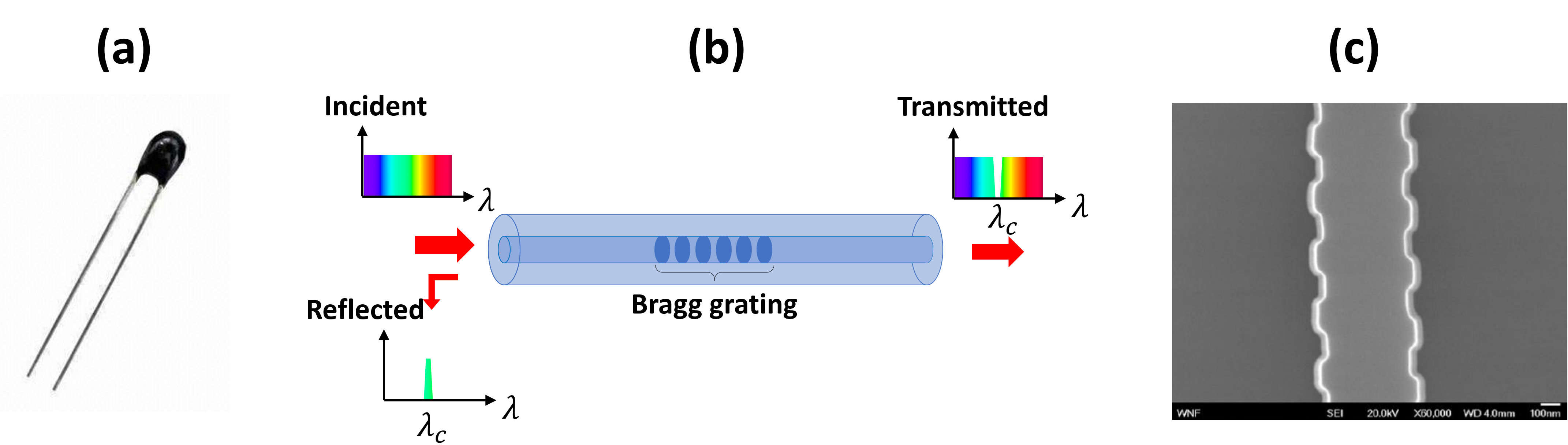
Typical thermistor in (a), fiber sensor with Bragg grating in (b) and in (c), an integrated waveguide with corrugated sidewalls (picture taken from the PDK documentation in PDKdoc).
These issues can be alleviated by relying on photonics-based temperature sensors. To achieve temperature sensing optically, a wavelength-selective element, i.e. a filter, is used. Such filters are typically realized with a fiber Bragg grating, depicted in Typical thermistor (b). As Typical thermistor (b) shows, light is coupled in the fiber towards the Bragg grating. Because the Bragg grating reflects light at a particular wavelength, there will be a dip in the transmission spectrum. Temperature changes will result in a refractive index change, thus shifting the wavelength at the transmission dip. Measuring the changes of this wavelength thus enables you to determine the temperature.
While these fiber-based temperature sensors have already been demonstrated and commercialized, their performance can be improved by realizing the same functionality in an integrated circuit fabricated in, for example, a SOI platform. While gratings in fiber are realised by alternating regions of different refractive index, in an integrated circuit, gratings are typically realised by corrugating waveguide sidewalls with a periodic function (see Typical thermistor (c)). Employing integrated WBGs not only makes sensors more compact compared to their fiber-based counterparts, it will also improve their sensitivity. This is due to the fact that, in silicon, refractive index changes resulting from temperature changes are more pronounced than in silica.
1.2. A successful WBG design: what is needed in IPKISS?
Now that you are convinced that the best way to way to fabricate a temperature sensor is by using WBGs in an integrated photonic chip, we will explain how using IPKISS will help you achieve this goal.
The design of a WBG all boils down to its basic building block: the unit cell of the grating. An example is depicted in Illustration of a rectangular unit cell (a).
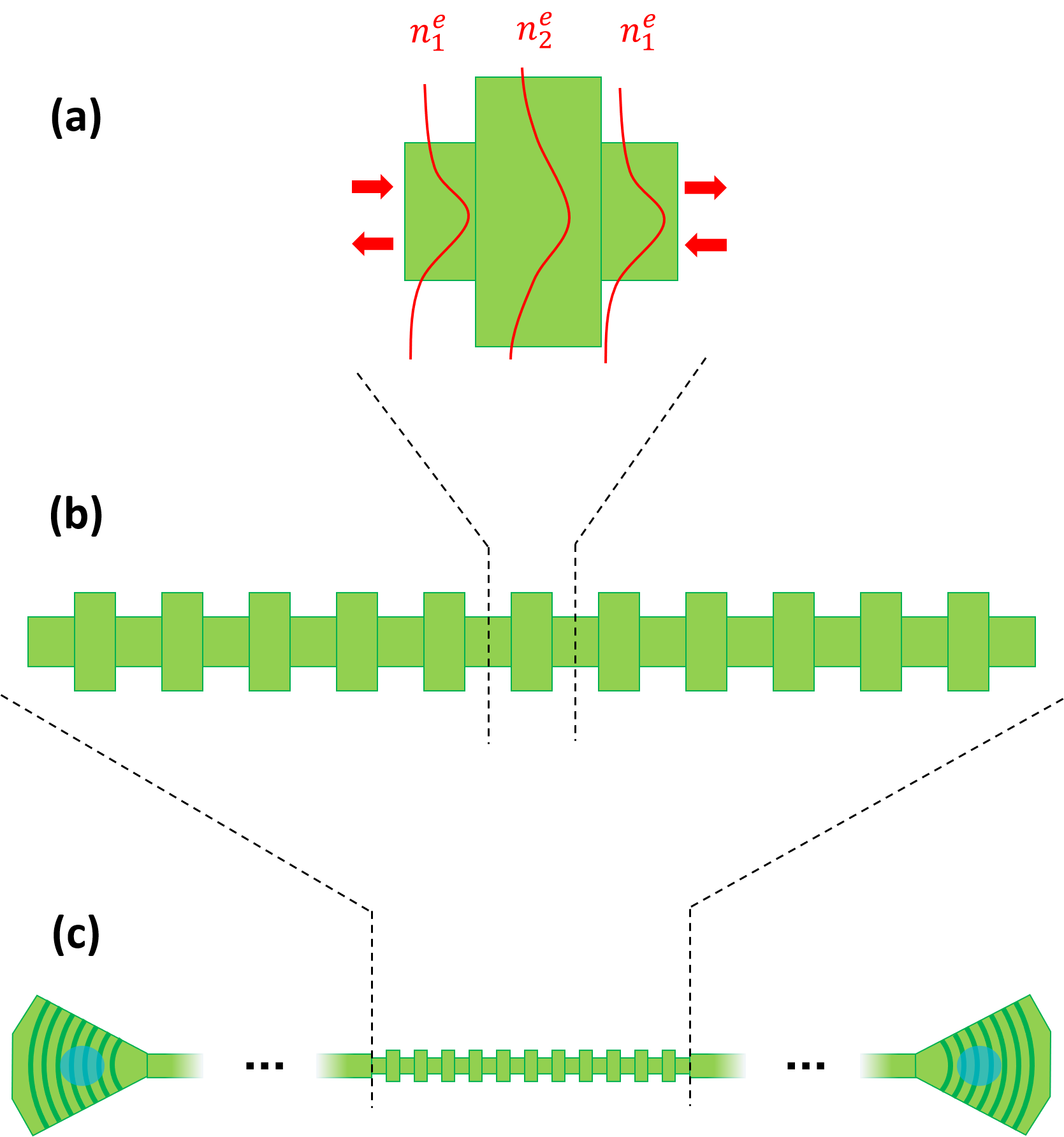
Illustration of a rectangular unit cell in (a), indicating the effective indices \(n_{1,2}^e\) and illustrating the different field profiles that are the cause of the reflections. (b) Full WBG. (c) WBG in a circuit with I/O ports - in this case grating couplers.
In this example, a rectangular unit cell is considered which consists of short waveguide sections with cross sections. Because of their alternating cross sections, the modes in the different sections will have different effective indices \(n_{1}^e\) and \(n_{2}^e\) and reflections will occur at the interfaces. Although the main focus of this tutorial will be using this rectangular unit cell, in IPKISS this design strategy can be applied to any unit cell of arbitrary shape, configuration and dimensions. Stitching a predefined number of these unit cells together then yields a WBG as seen in Illustration of a rectangular unit cell (b). Around the center wavelength of the WBG, the reflections from all consecutive unit cells constructively interfere, thus fully reflecting the incoming signal. As explained earlier, the temperature fluctuations induce refractive index changes in the unit cells, thus changing the conditions for which the reflections constructively interfere. As a consequence, the center wavelength of the WBG shifts. The amount by which the center wavelength shifts for a given temperature change is called the sensitivity and depends on the unit cell configuration. Maximizing the sensitivity is the aim of our integrated temperature sensor, so we will need to optimise the unit cell configuration and thus the WBG accordingly. Finally, the WBG is not a standalone device - it still needs to communicate with an external light source and a detector - so we need to place the WBG in a circuit with, for example, grating couplers (see Illustration of a rectangular unit cell (c)).
While this may sound complex at first, the good news is that IPKISS is perfectly suited to help you design and layout these kinds of circuits. Indeed, due to its flexibility and built-in functionalities (i.e. custom or built-in python scripts), IPKISS can greatly simplify and automate the design process. For designing our temperature sensor in particular, we need the following scripts:
A script that helps you define the layout of the unit cell. The layout properties of the unit cell will be used in the following scripts to generate the circuit model.
A script that calculates the S-matrices of the unit cell for different wavelengths and temperatures. These S-matrices describe the optical behavior of the unit cell, such as, in our case, the transmission and reflection spectra for different temperatures (see the tutorial about S-matrices in Add a circuit model to the MMI for more information).
A script that fits the simulation data with a set of polynomials. The simulations can result in a large number of data points. For this reason, it is recommended to fit the data with polynomials containing only a few coefficients. This not only saves memory, but will also speed up the circuit model generation.
A script that saves the polynomial coefficients. The data from the polynomial fits for a given unit cell configuration need to be stored in a .txt or other datafile. This will ensure that when the component is reused, the S-matrices don’t need to be recalculated.
A script that reads the polynomial coefficients and creates the circuit model of the unit cell. Since the data describing the unit cell is stored in a datafile, the data needs to be loaded to then be used to calculate the wavelength polynomial coefficients for the transmission and reflection spectra of the S matrix. This is requirement for Caphe, Luceda IPKISS’s circuit simulator.
A script that finds the optimal unit cell configuration for yielding the highest temperature sensitivity of the WBG.
A script that generates the layout of the WBG for a given unit cell.
A script that generates the circuit model of the WBG based on the physical properties of the unit cell.
A script that places the WBG in a workable circuit with fiber couplers, generating its layout and circuit model.
The above scripts are already provided by Luceda Academy.
Therefore, in the following sections, we will explain how the code works and how to employ the scripts to create your design.
The scripts used in this tutorial are provided in the luceda-academy/training/topical_training/wbg_temp_sensor folder, while the code for the unit cell and WBG are provided in luceda-academy/libraries/pteam_library_siepic.