1. MZI lattice filter
In this section, we will explain how to design a lattice filter based on Mach-Zender interferometers (MZI) using Luceda IPKISS.
1.1. Directional coupler
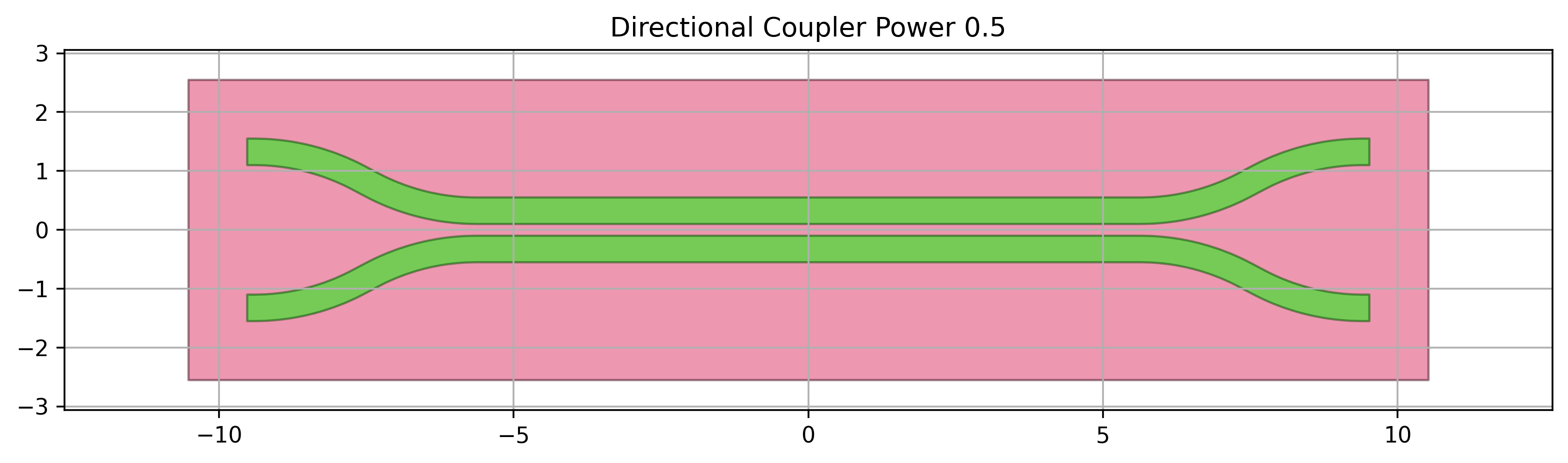
The basic building block of an MZI is the directional coupler.
In this case, we use SiDirectionalCouplerSPower from SiFab, the demonstration pdk distributed with this training material.
This class is useful as it has a precomputed model, which is used to calculate the correct length of the directional coupler for a given power coupling coefficient into the cross arm.
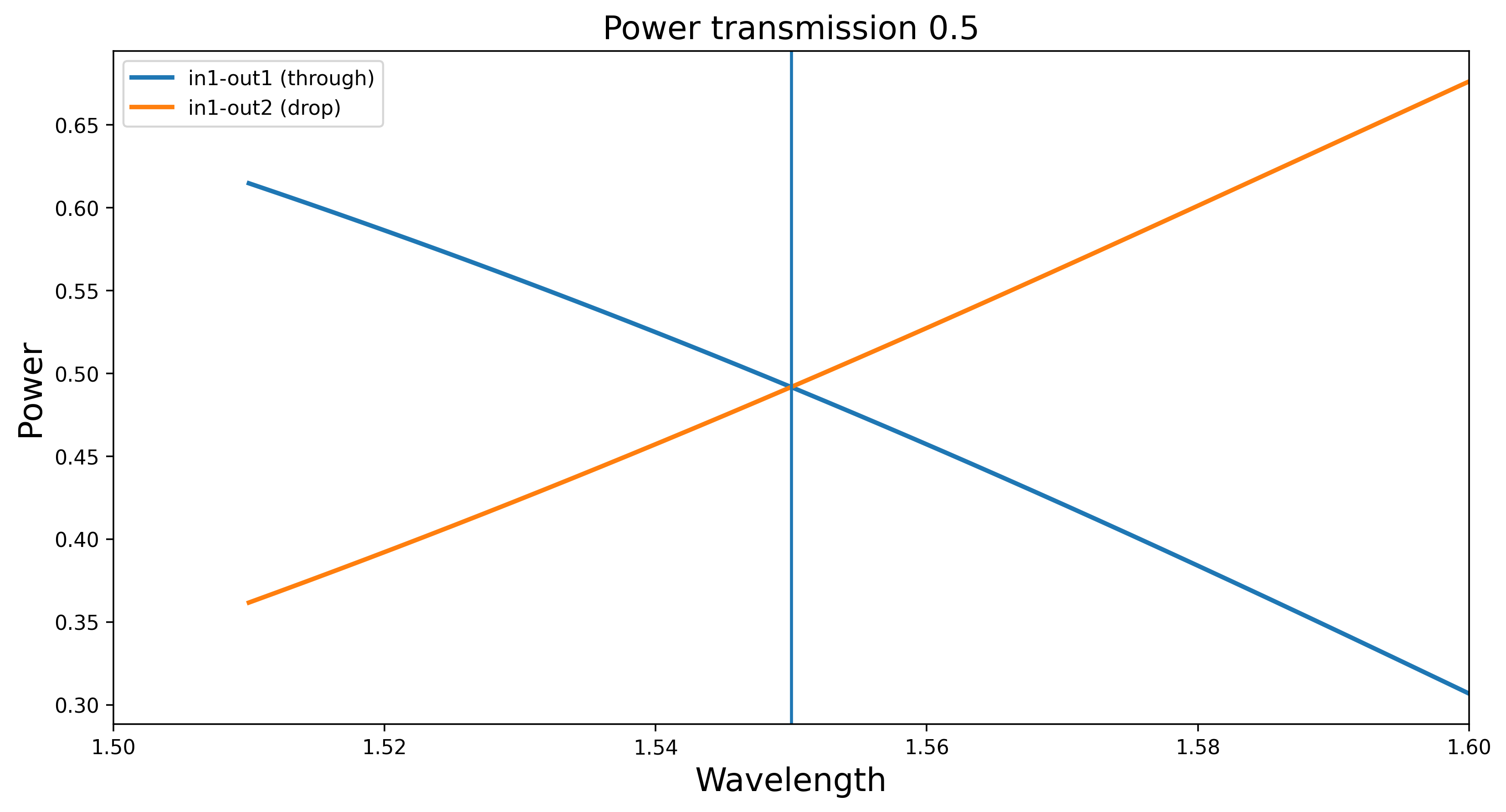
We can visualize this component, run a circuit simulation and plot the transmission.
For more info on directional couplers available in SiFab,
have a look at Directional coupler.
from si_fab import all as pdk
import numpy as np

dc = pdk.SiDirectionalCouplerSPower(power_fraction=0.5, target_wavelength=1.55)
dc_lv = dc.Layout()
dc_lv.visualize(annotate=True)

dc_cm = dc.CircuitModel()

wavelengths = np.linspace(1.51, 1.6, 500)
S = dc_cm.get_smatrix(wavelengths=wavelengths)
S.visualize(term_pairs=[("in1", "out1"), ("in1", "out2")], title="Transmission")
print("Done")
1.2. MZI lattice filter
Now we can use this directional coupler to build an MZI lattice filter.
To achieve this, we define a Python class that inherits from i3.Circuit and call it MZILatticeFilter.
This lattice filter is a parametric circuit with customizable number of cascaded MZIs.
The lengths of the directional couplers used for the MZIs are automatically calculated by providing a list of power coupling coefficients.
class MZILatticeFilter(i3.Circuit):
    """Mach-Zender interferometer lattice filter based on directional couplers with different power
    coupling.
    The number of power couplings should be equal to the number of delay lengths plus 1.
    """

    directional_couplers = i3.ChildCellListProperty(doc="list of directional couplers")
    center_wavelength = i3.PositiveNumberProperty(default=1.55, doc="Center wavelength")
    delay_lengths = i3.ListProperty(default=[100.0], doc="List of delay lengths")
    bend_radius = i3.PositiveNumberProperty(default=5.0, doc="Bend radius")
    phase_error_width_deviation = i3.NonNegativeNumberProperty(default=0.0)
    phase_error_correlation_length = i3.NonNegativeNumberProperty(default=0.0)

    def _default_directional_couplers(self):
        power_couplings = [0.5, 0.5]
        dir_couplers = [
            pdk.SiDirectionalCouplerSPower(
                name=self.name + f"dc_{cnt}",
                power_fraction=p,
                target_wavelength=self.center_wavelength,
            )
            for cnt, p in enumerate(power_couplings)
        ]
        return dir_couplers

    def _default_specs(self):
        # store for later
        dcs = [dc.Layout() for dc in self.directional_couplers]
        specs = [i3.Inst(f"dc_{cnt}", dc) for cnt, dc in enumerate(dcs)]

        distance = 4 * self.bend_radius
        specs += [
            i3.Place(f"dc_{cnt}:in1", (distance, 0), relative_to=f"dc_{cnt - 1}:out1")
            for cnt in range(1, len(self.directional_couplers))
        ]

        for cnt, delay_length in enumerate(self.delay_lengths):
            if delay_length > 0:
                l_top = delay_length / 2
                l_bot = 0
            else:
                l_top = 0
                l_bot = -delay_length / 2
            p1 = f"dc_{cnt}:out1"
            p2 = f"dc_{cnt + 1}:in1"
            # modify the trace template of the port
            p1_port = dcs[cnt].ports["out1"]
            tt = p1_port.trace_template
            tt_mod = tt.cell.modified_copy()
            tt_mod.CircuitModel(
                phase_error_width_deviation=self.phase_error_width_deviation,
                phase_error_correlation_length=self.phase_error_correlation_length,
            )
            specs.append(
                i3.ConnectManhattan(
                    p1,
                    p2,
                    trace_template=tt_mod,
                    bend_radius=self.bend_radius,
                    control_points=[i3.H(-2 * self.bend_radius - l_bot, relative_to=p1)],
                    min_straight=0,
                    start_straight=0,
                    end_straight=0,
                )
            )

            p1 = f"dc_{cnt}:out2"
            p2 = f"dc_{cnt + 1}:in2"

            p1_port = dcs[cnt].ports["out2"]
            tt = p1_port.trace_template
            tt_mod = tt.cell.modified_copy()
            tt_mod.CircuitModel(
                phase_error_width_deviation=self.phase_error_width_deviation,
                phase_error_correlation_length=self.phase_error_correlation_length,
            )
            specs.append(
                i3.ConnectManhattan(
                    p1,
                    p2,
                    trace_template=tt_mod,
                    bend_radius=self.bend_radius,
                    control_points=[i3.H(2 * self.bend_radius + l_top, relative_to=p1)],
                    min_straight=0,
                    start_straight=0,
                    end_straight=0,
                )
            )

        return specs

    def _default_exposed_ports(self):
        exposed_ports = {
            "dc_0:in1": "in1",
            "dc_0:in2": "in2",
            f"dc_{len(self.delay_lengths)}:out1": "out1",
            f"dc_{len(self.delay_lengths)}:out2": "out2",
        }
        return exposed_ports
Let’s analyze the code above:
Properties. We defined a list of properties that are used to design the MZI lattice filters. The length of the list provided in
power_couplingsdetermines how many directional couplers are used to design the lattice filter. If 5 values are provided for the power coupling coefficients, then 4 values should be provided for thedelay_lengthsto be used to connect the 5 directional couplers to each other. The phase error properties can be used to perform a variability analysis of the MZI lattice filter.Default directional couplers. In
_default_directional_couplerswe instantiate as many directional couplers as provided inpower_couplings. As mentioned earlier, the default directional coupler used in this example isSiDirectionalCouplerSPowerfrom SiFab.i3.Circuit properties. Next, the properties needed to create a circuit with
i3.Circuitare specified:The directional couplers are added to the list of specs that form our circuit in
_default_specs.The placement (of the directional couplers) and routing (connectors between the directional couplers) specifications are provided in
_default_specs. A connector which is used to draw the arms connecting the directional couplers to each other implements the delay length given by the values in thedelay_lengths.The external ports of the final MZI lattice filter are exposed using
_default_exposed_ports.
The connectivity defined in i3.Circuit is automatically used to extract the netlist of the circuit and to perform circuit simulations.