2. CWDM based on cascaded MZI lattice filters
In this section, we will explain how to combine MZI lattice filters to obtain demultiplexers with the desired number of stages and channels.
2.1. Designing our first lattice filter
In the following code we use a series of power couplings and delay lengths to design and layout a 2x2 flatband demultiplexer with a certain FSR and center frequency. In the first step, we use the power couplings from this paper (Dwivedi et al. “Coarse Wavelength Division Multiplexer on Silicon-On-Insulator for 100 GbE,” 2015 GFP, pp. 9-10, doi: 10.1109/Group4.2015.7305928.) which were chosen to achieve a maximally flat response.
The delay lengths are calculated from the effective index (\(n_{eff}\)), the group index (\(n_{g}\)), the center wavelength (\(\lambda_{center}\)) and the chosen FSR.
With the help of the following formulas:
\(L = \dfrac{\lambda _{center} ^2}{n_g FSR}\)
embedded in the helper function get_mzi_delta_length_from_fsr and
\(L_{\pi} = \dfrac{\lambda _{center}}{2 n_eff}\)
embedded in the helper function get_length_pi
we can calculate the delay lengths, which are \([L\), \(2 L\), \((- 2 L + L_{\pi})\), \(- 2 L]\).
# Free Spectral Range
fsr = 0.01
# Center Wavelength
center_wavelength = 1.55

# Directional coupler class
coupler_class = pdk.SiDirectionalCouplerSPower
trace_template = coupler_class().get_default_view(i3.LayoutView).ports[0].trace_template.cell

# Get the length from the FSR
length = get_mzi_delta_length_from_fsr(
    trace_template=trace_template,
    fsr=fsr,
    center_wavelength=center_wavelength,
)

# Get delta pi
length_pi = get_length_pi(center_wavelength=center_wavelength, trace_template=trace_template)

# Coupling coefficients and delay lengths
power_couplings = [0.5, 0.13, 0.12, 0.5, 0.25]
delay_lengths = [length, 2 * length, -(2 * length + length_pi), -2 * length]

dcs = []
for p in power_couplings:
    dc = coupler_class(target_wavelength=center_wavelength, power_fraction=p)
    dcs.append(dc)
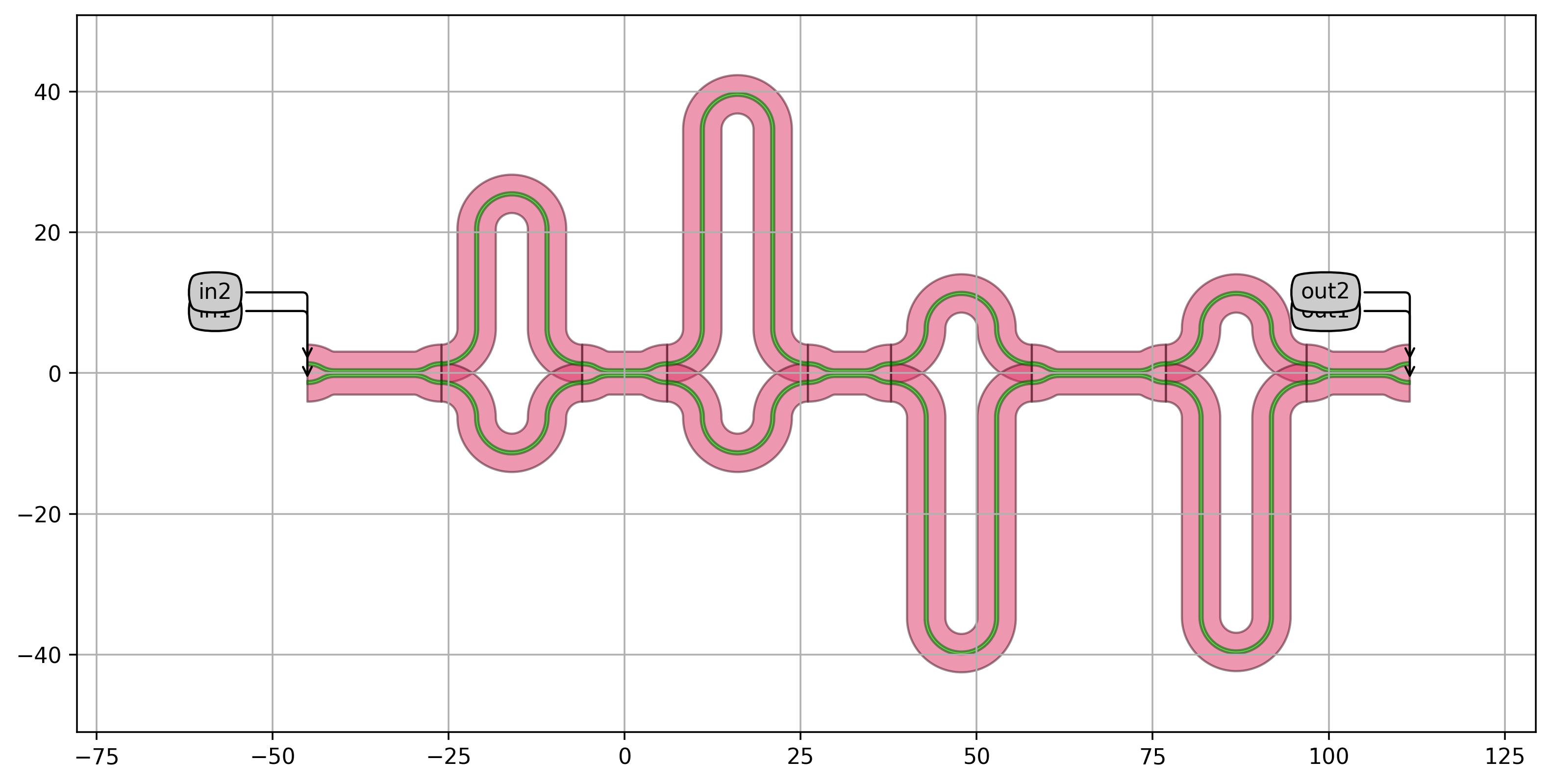
In the next step, we use the MZILatticeFilter class to generate a lattice filter based on the calculated DC’s and delay lengths and write the result to gds.
# Creating the lattice filter and writing to gds
mzi_lattice = MZILatticeFilter(
    directional_couplers=dcs,
    delay_lengths=delay_lengths,
)

mzi_lattice_lv = mzi_lattice.Layout()
mzi_lattice_lv.visualize(annotate=True)
mzi_lattice_lv.write_gdsii("lattice_example1.gds")
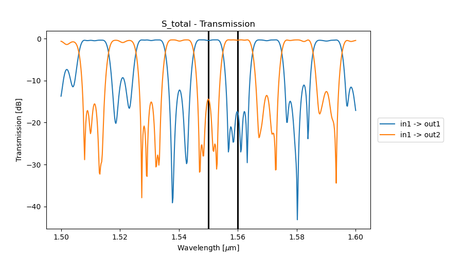
Finally, we simulate the lattice filter.
# Simulation of the lattice filter
cell_cm = mzi_lattice.CircuitModel()
wavelengths = np.linspace(1.5, 1.6, 1001)
S = cell_cm.get_smatrix(wavelengths=wavelengths)
channels = [center_wavelength + cnt * fsr / 2 for cnt in range(2)]
# Extract passband peak information based on the S-parameters
# Using i3.SpectrumAnalyzer
sa = i3.SpectrumAnalyzer(
S,
input_port_mode="in1",
output_port_modes=["out1", "out2"],
dB=True,
peak_threshold=-5,
bandpass=True,
)
peaks = sa.peaks()
peaks_out1 = peaks["out1"]["wavelength"]
peaks_out2 = peaks["out2"]["wavelength"]
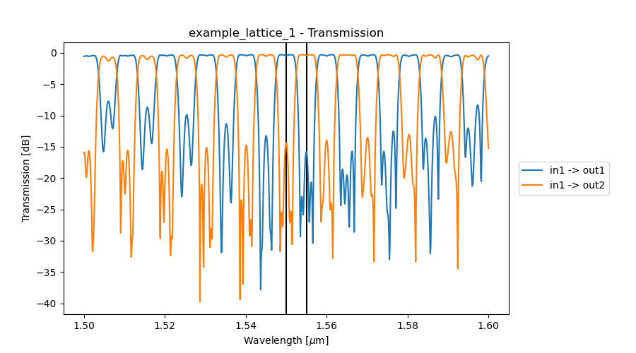
# Plot the transmission spectra, extracted peaks and specified channels
name = "example_lattice_1"
save_dir = os.path.join(os.path.dirname(os.path.realpath(__file__)), "_images", name)
if not os.path.exists(save_dir):
os.makedirs(save_dir)
S.visualize(
term_pairs=[("in1", "out1"), ("in1", "out2")],
scale="dB",
ylabel="Transmission [dB]",
title=f"{name} - Transmission",
save_name=os.path.join(save_dir, "S_total.png"),
)
2.2. Implementing the lattice filter as a class
Once the implementation strategy is chosen, we can directly inherit from the MZI lattice filter defined in the previous section to design a two-way wavelength demultiplexer.
We define a Python class that inherits from MZILatticeFilter to create a demultiplexer with 50% of the given free spectral range (FSR) at the specified center wavelength.
class Mux2(MZILatticeFilter):
    """Two-way wavelength demultiplexer with a passband of 50% of the FSR at the center_wavelength.
    This component inherits from MZILatticeFilter.
    Power couplings are taken from 'Coarse Wavelength Division Multiplexer on Silicon-On-Insulator
    for 100 GbE': DOI:10.1109/group4.2015.7305928
    """

    _name_prefix = "MUX2"

    power_couplings = i3.LockedProperty(default=[0.5, 0.13, 0.12, 0.5, 0.25])
    delay_lengths = i3.LockedProperty()
    bend_radius = i3.LockedProperty()
    fsr = i3.PositiveNumberProperty(default=0.01, doc="Free spectral range of the MUX2")
    center_wavelength = i3.PositiveNumberProperty(default=1.55, doc="Center wavelength")

    def _default_directional_couplers(self):
        dir_couplers = [
            pdk.SiDirectionalCouplerSPower(
                name=self.name + f"dc_{cnt}",
                power_fraction=p,
                target_wavelength=self.center_wavelength,
            )
            for cnt, p in enumerate(self.power_couplings)
        ]
        return dir_couplers

    def _default_delay_lengths(self):
        tt = self.directional_couplers[0].get_default_view(i3.LayoutView).ports[0].trace_template.cell
        length = get_mzi_delta_length_from_fsr(
            center_wavelength=self.center_wavelength,
            fsr=self.fsr,
            trace_template=tt,
        )

        length_pi = get_length_pi(center_wavelength=self.center_wavelength, trace_template=tt)

        delay_lengths = [length, 2 * length, -(2 * length + length_pi), -2 * length]
        return delay_lengths

    def _default_bend_radius(self):
        return 5.0
The properties of this class are:
power_couplings: this is a locked property.delay_lengths: this is a locked property.bend_radius: this is a locked property. Its default value is 5 um.fsr: this property is not locked and can be changed when instantiating the PCell. The default value is 0.01.center_wavelength: this property is not locked. The default value is 1.55 um.
We can now instantiate this PCell and simulate it:
Instantiate the component, its layout and visualize it.
luceda-academy/training/topical_training/wdm_transmitter_mzi/mux2.py# Writing the layout cell = pt_lib.Mux2( name="MUX2", fsr=0.02, center_wavelength=1.55, ) cell_lv = cell.Layout() cell_lv.visualize(annotate=True) cell_lv.write_gdsii("mux2.gds")
Instantiate and simulate the circuit.
    # Simulating the circuit
    wavelengths = np.linspace(1.5, 1.6, 501)
    cell_cm = cell.CircuitModel()
    S = cell_cm.get_smatrix(wavelengths=wavelengths)
Plot the transmission between the input port
in1and the two output portsout1andout2.