Directional coupler
SiFab contains seven different directional couplers:
DirectionalCoupler: fully parametric directional coupler that can take any trace template.
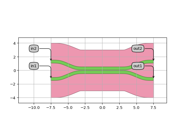
SiDirectionalCouplerU: directional coupler with a silicon wire trace template and a U-shape. It has fixed properties, but variable length of the straight section.
SiDirectionalCouplerS: directional coupler with a silicon wire trace template and an S-shape. It has fixed properties, but variable length of the straight section.
SiNDirectionalCouplerS: directional coupler with a silicon nitride wire trace template and an S-shape. It has fixed properties, but variable length of the straight section.
SiDirectionalCouplerUPower: directional coupler with a silicon wire trace template and a U-shape. The desired power split ratio between the two arms can be specified and the correct length is automatically calculated.
SiDirectionalCouplerSPower: directional coupler with a silicon wire trace template and an S-shape. The desired power split ratio between the two arms can be specified and the correct length is automatically calculated.
SiNDirectionalCouplerSPower: directional coupler with a silicon nitride wire trace template and an S-shape. The desired power split ratio between the two arms can be specified and the correct length is automatically calculated.
The section Simulation and regeneration of the data files explains how to simulate and regenerate the simulation data of these directional couplers.
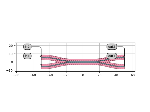
DirectionalCoupler
This is a directional coupler with fully customisable layout.
Custom functions can be passed as routing_method.
This function is used to draw the bent section of the directional coupler and takes three parameters as input: bend_width, bend_height and adiabatic_angle.
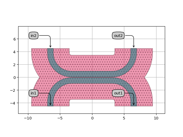
The currently available routing methods are called ShapeDCBend, to obtain a U-shaped directional coupler, and ShapeDCSBend, to obtain an S-shaped directional coupler.
This class doesn’t have a circuit model as the directional coupler has not been simulated and optimized.
Reference
Click on the name of the component below to see the complete PCell reference.
Directional coupler with customisable layout. |
Click on the name of the functions below to see the complete API reference of the two available routing methods.
Method that returns a Bezier bend to be used to build the directional coupler. |
|
Method that returns a Bezier s-bend to be used to build the directional coupler. |
Example
from si_fab import all as pdk
from si_fab.components.dir_coupler.pcell.cell_utils import ShapeDCSBend, ShapeDCBend

dc1 = pdk.DirectionalCoupler(
    trace_template=pdk.SiWireWaveguideTemplate(),
    routing_method=ShapeDCSBend,
    straight_length=5.0,
    spacing=0.1,
    bend_length=5.0,
    bend_height=1.0,
    adiabatic_angle=5.0,
)

dc1_lv = dc1.Layout()
dc1_lv.visualize(annotate=True)

dc2 = pdk.DirectionalCoupler(
    trace_template=pdk.SiNWireWaveguideTemplate(),
    routing_method=ShapeDCBend,
    straight_length=5.0,
    spacing=0.1,
    bend_length=4.0,
    adiabatic_angle=5.0,
)

dc2_lv = dc2.Layout()
dc2_lv.visualize(annotate=True)
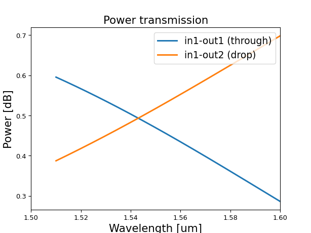
SiDirectionalCouplerU
This directional coupler inherits from DirectionalCoupler and uses a Bezier bend as standard routing method for the bent section.
This directional coupler uses the trace template SiWireWaveguideTemplate.
All the properties, aside from straight_length, are locked and have been optimized and simulated in the wavelength range between 1500 nm and 1600 nm using Ansys Lumerical FDTD and CST Studio Suite ®.
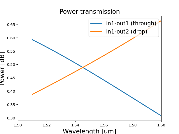
After the simulation, a fitting of the transmission and of the coupling parameters (\(\kappa\) and \(\kappa _0\)) is performed as a function of length for all the wavelengths between 1500 nm and 1600 nm. The coefficients of the polynomial fit are stored and used by the circuit model of this component to run Caphe simulations with the desired length and at the desired wavelength. For this component, an analytical model with the following equations is used:
where \(t\) is the transmission, \(\kappa_0\) is the coupling for a directional coupler with \(L=0\), \(\kappa\) is the coupling constant per unit of length. \(t\), \(\kappa_0\), \(\kappa\) are dispersive with respect to wavelength.
By default, the results of the fitting of the Ansys Lumerical FDTD simulation are stored and used for the circuit simulation. However, this can be changed by regenerating the fit using the simulation data from the CST Studio Suite ® simulations (see Simulation and regeneration of the data files:).
Reference
Click on the name of the component below to see the complete PCell reference.
Silicon wire directional coupler with a U-shape, where all the properties aside from the length (straight_length) are optimized and locked. |
Example
from si_fab import all as pdk
import numpy as np
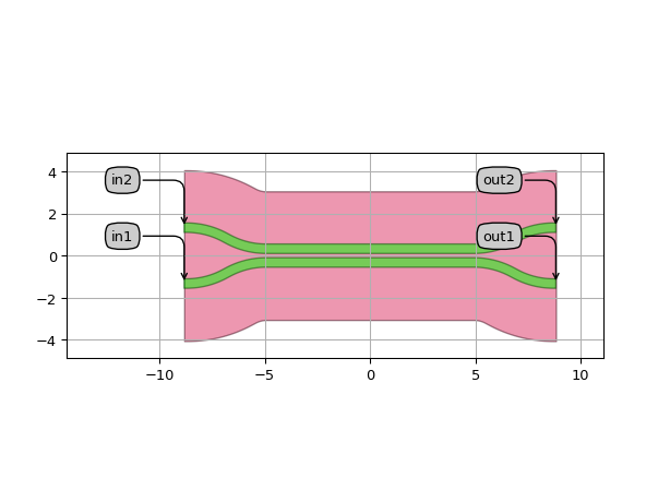
dc = pdk.SiDirectionalCouplerU(straight_length=8.0)
dc_lv = dc.Layout()
dc_lv.visualize(annotate=True)
dc_cm = dc.CircuitModel()
wavelengths = np.linspace(1.51, 1.6, 500)
S = dc_cm.get_smatrix(wavelengths=wavelengths)
S.visualize(
term_pairs=[
("in1", "out1"), # through
("in1", "out2"), # drop
],
scale="dB",
title="Power transmission",
)
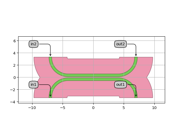
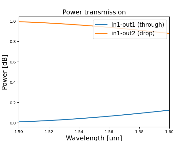
SiDirectionalCouplerS
This directional coupler follows the same logic as SiDirectionalCouplerU and also uses SiWireWaveguideTemplate`.
It inherits from DirectionalCoupler and uses a Bezier s-bend as standard routing method for the bent section.
All the properties, aside from straight_length, are locked and have been optimized and simulated in the wavelength range between 1500 nm and 1600 nm using Ansys Lumerical FDTD and CST Studio Suite ®.
By default, the results of the fitting of the Ansys Lumerical FDTD simulation are stored and used for the circuit simulation.
However, this can be changed by regenerating the fit using the simulation data from the CST Studio Suite ® simulations (see Simulation and regeneration of the data files:).
Reference
Click on the name of the component below to see the complete PCell reference.
Silicon wire directional coupler with a S-shape, where all the properties aside from the length (straight_length) are optimized and locked. |
Example
from si_fab import all as pdk
import numpy as np

dc = pdk.SiDirectionalCouplerS(straight_length=10.0)
dc_lv = dc.Layout()
dc_lv.visualize(annotate=True)

dc_cm = dc.CircuitModel()

wavelengths = np.linspace(1.51, 1.6, 500)
S = dc_cm.get_smatrix(wavelengths=wavelengths)
S.visualize(
    term_pairs=[
        ("in1", "out1"),  # through
        ("in1", "out2"),  # drop
    ],
    scale="dB",
    title="Power transmission",
    xrange=(1.5, 1.6),
)

SiNDirectionalCouplerS
This directional coupler is similar to SiDirectionalCouplerS except that it uses SiNWireWaveguideTemplate as the trace template so as to have silicon nitride directional couplers.
Reference
Click on the name of the component below to see the complete PCell reference.
Silicon nitride wire directional coupler with a S-shape, where all the properties aside from the length (straight_length) are optimized and locked. |
Example
from si_fab import all as pdk
import numpy as np

dc = pdk.SiNDirectionalCouplerS(straight_length=20.0)
dc_lv = dc.Layout()
dc_lv.visualize(annotate=True)

dc_cm = dc.CircuitModel()

wavelengths = np.linspace(1.5, 1.6, 500)
S = dc_cm.get_smatrix(wavelengths=wavelengths)
S.visualize(
    term_pairs=[
        ("in1", "out1"),  # through
        ("in1", "out2"),  # drop
    ],
    scale="dB",
    title="Power transmission",
)
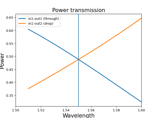
SiDirectionalCouplerUPower
This directional coupler is a PCell that uses the fitted model to obtain a specified fraction of the output power coupled into the cross arm (power_fraction) at the desired wavelength (target_wavelength).
It inherits from SiDirectionalCouplerU, therefore the directional coupler is built using a Bezier bend as default routing method and the Caphe simulation is performed using the fitting data generated by simulating SiDirectionalCouplerU.
Reference
Click on the name of the component below to see the complete PCell reference.
PCell for a silicon wire directional coupler that uses the fitted model to achieve a power coupling at a target wavelength |
Example
from si_fab import all as pdk
from ipkiss3 import all as i3
import numpy as np
import matplotlib.pyplot as plt
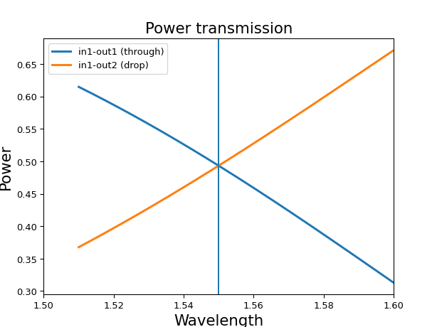
dc = pdk.SiDirectionalCouplerUPower(power_fraction=0.5, target_wavelength=1.55)
dc_lv = dc.Layout()
dc_lv.visualize(annotate=True)
dc_cm = dc.CircuitModel()
wavelengths = np.linspace(1.51, 1.6, 500)
S = dc_cm.get_smatrix(wavelengths=wavelengths)
plt.figure()
plt.plot(wavelengths, i3.signal_power(S["out1", "in1"]), linewidth=2.2, label="in1-out1 (through)")
plt.plot(wavelengths, i3.signal_power(S["out2", "in1"]), linewidth=2.2, label="in1-out2 (drop)")
plt.axvline(x=dc.target_wavelength)
plt.title("Power transmission", fontsize=16)
plt.xlabel("Wavelength", fontsize=16)
plt.ylabel("Power", fontsize=16)
plt.xlim(1.5, 1.6)
plt.legend(fontsize=14, loc=1)
plt.legend()
plt.show()

SiDirectionalCouplerSPower
This directional coupler follows the same logic as SiDirectionalCouplerUPower.
It inherits from SiDirectionalCouplerS, therefore it is built using a Bezier s-bend as default routing method and the Caphe simulation is performed using the fitting data generated by simulating SiDirectionalCouplerS.
Reference
Click on the name of the component below to see the complete PCell reference.
PCell for a silicon wire directional coupler that uses the fitted model to achieve a power coupling at a target wavelength. |
Example
from si_fab import all as pdk
from ipkiss3 import all as i3
import numpy as np
import matplotlib.pyplot as plt

dc = pdk.SiDirectionalCouplerSPower(power_fraction=0.5, target_wavelength=1.55)
dc_lv = dc.Layout()
dc_lv.visualize(annotate=True)

dc_cm = dc.CircuitModel()

wavelengths = np.linspace(1.51, 1.6, 500)
S = dc_cm.get_smatrix(wavelengths=wavelengths)
plt.figure()
plt.plot(wavelengths, i3.signal_power(S["out1", "in1"]), linewidth=2.2, label="in1-out1 (through)")
plt.plot(wavelengths, i3.signal_power(S["out2", "in1"]), linewidth=2.2, label="in1-out2 (drop)")
plt.axvline(x=dc.target_wavelength)
plt.title("Power transmission", fontsize=16)
plt.xlabel("Wavelength", fontsize=16)
plt.ylabel("Power", fontsize=16)
plt.xlim(1.5, 1.6)
plt.legend(fontsize=14, loc=1)
plt.legend()
plt.show()
SiNDirectionalCouplerSPower
This directional coupler follows the same logic as SiDirectionalCouplerUPower and SiDirectionalCouplerSPower.
It inherits from SiNDirectionalCouplerS, therefore it is built using a Bezier s-bend as default routing method and the Caphe simulation is performed using the fitting data generated by simulating SiNDirectionalCouplerS.
Reference
Click on the name of the component below to see the complete PCell reference.
PCell for a silicon wire directional coupler that uses the fitted model to achieve a power coupling at a target wavelength. |
Example
from si_fab import all as pdk
from ipkiss3 import all as i3
import numpy as np
import matplotlib.pyplot as plt

dc = pdk.SiDirectionalCouplerSPower(power_fraction=0.5, target_wavelength=1.55)
dc_lv = dc.Layout()
dc_lv.visualize(annotate=True)

dc_cm = dc.CircuitModel()

wavelengths = np.linspace(1.51, 1.6, 500)
S = dc_cm.get_smatrix(wavelengths=wavelengths)
plt.figure()
plt.plot(wavelengths, i3.signal_power(S["out1", "in1"]), linewidth=2.2, label="in1-out1 (through)")
plt.plot(wavelengths, i3.signal_power(S["out2", "in1"]), linewidth=2.2, label="in1-out2 (drop)")
plt.axvline(x=dc.target_wavelength)
plt.title("Power transmission", fontsize=16)
plt.xlabel("Wavelength", fontsize=16)
plt.ylabel("Power", fontsize=16)
plt.xlim(1.5, 1.6)
plt.legend(fontsize=14, loc=1)
plt.legend()
plt.show()
Simulation and regeneration of the data files
The simulations performed on SiDirectionalCouplerU and SiDirectionalCouplerS with Ansys Lumerical FDTD and with CST Studio Suite ® can be regenerated if deeper exploration of these components needs to be carried out.
The regeneration can be performed using the regenerate_dc() function using the script regenerate_directional_coupler_u.py or regenerate_directional_coupler_s.py contained in si_fab/components/dir_coupler/regeneration.
The user can specify the following options:
dir_coupler_class: the directional coupler to regenerate. The name should not contain parentheses ().lengths: numpy array of the lengths to be resimulated, refitted or replotted.wavelengths: list of wavelengths at which the simulation should be run.sim_sw: simulation software to be used for the simulation. The only accepted inputs are “Lumerical” and “CST”.resimulate: boolean. If True, the directional coupler will be simulated for all thelengthsat all thewavelengths. The S-matrix results and the simulation files are stored in a smatrix.s4p file in data/component_name/sim_sw/lengthX.X.refit: boolean. If True, it performs a fitting of the data contained in the smatrix.s4p files for the specified lengths and at the specified wavelengths. The polynomial coefficients are stored in a params.json file in data/component_name/model. This file is loaded by Caphe to perform circuit simulations.plot: boolean. If True, it plots the results of the simulation and of the fitting, after these are done.
Reference
Click on the name of the functions below to see the complete API reference of the simulation and regeneration recipes.
|
Simulation recipe for a directional coupler in Lumerical FDTD. |
|
Simulation recipe for a directional coupler in CST Studio Suite (R). |
|
Function that allows to resimulate, refit and plot the results of the directional coupler specified in dir_coupler_class. |
Note
The above simulation results are artificial results as they’re based on fictional technology and components. These only serve demonstration purposes.