Mach-Zehnder modulator
SiFab contains one Mach-Zehnder modulator (MZM):
MZModulator: a fully parametric MZM, with phase shifters on each branch.
The section Model and simulation recipes explains how to simulate the MZM.
MZModulator
This device is based on a Mach-Zehnder interferometer, where the light is first split in two branches and is then recombined by interference. On each branch, a phase shifter is placed to control the relative phase shift of the light between the two branches. This allows to modulate the phase in order to achieve constructive or destructive interference, which results in an amplitude modulation.
The light is first split in two using a splitter, which can be provided through the splitter property.
A taper is used to transition from the waveguide mode in the splitter wire waveguide to the waveguide mode in the rib waveguide of the phase shifters.
The phase shifter are controlled by the phaseshifter property.
The distance between the splitter and the phase shifter on each arm is controlled through the property spacing_x.
The two arms of the MZM are designed to have a \(\pi / 2\)-length difference at center_wavelength, so that the modulator has maximum extinction ratio at center_wavelength, which is the wavelength of operation.
Both arms are equipped with waveguide heaters controlled by the property heater to make sure that the offset of \(\pi/2\) can be maintained over different operating conditions.
The heaters are connected using a M1M2 wire with width given by heater_elpath_width.
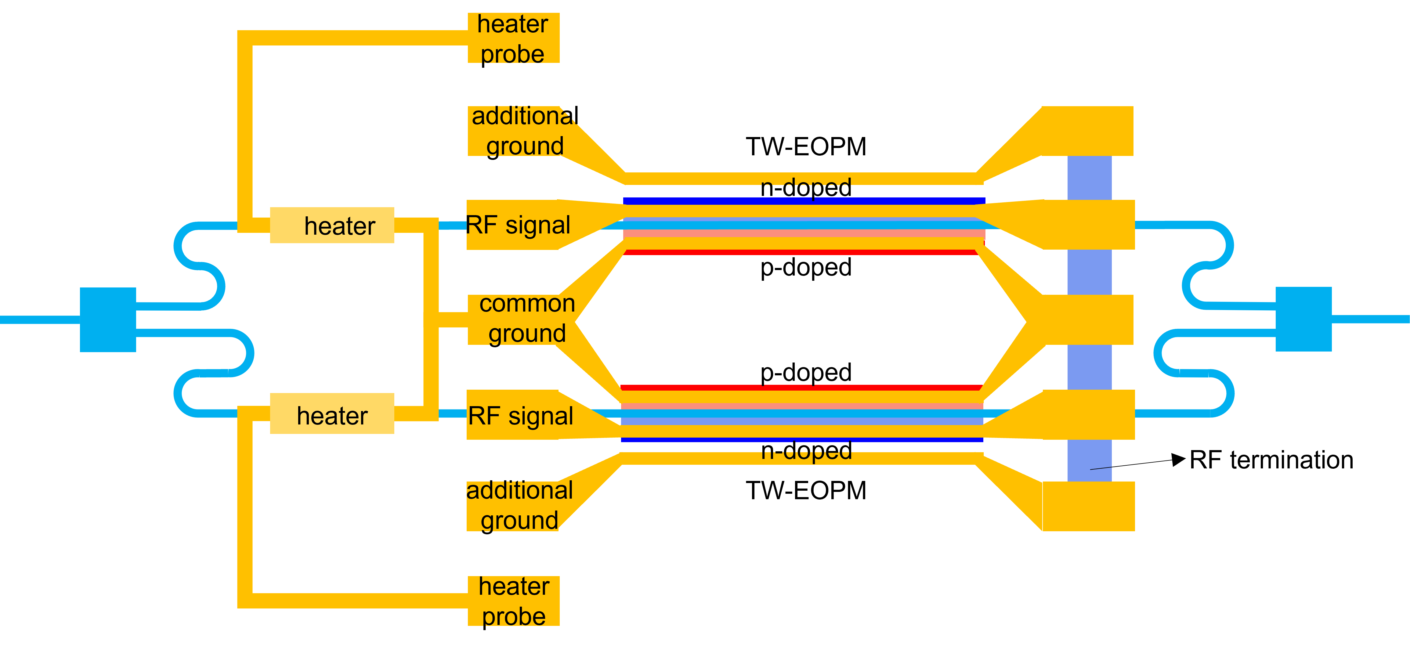
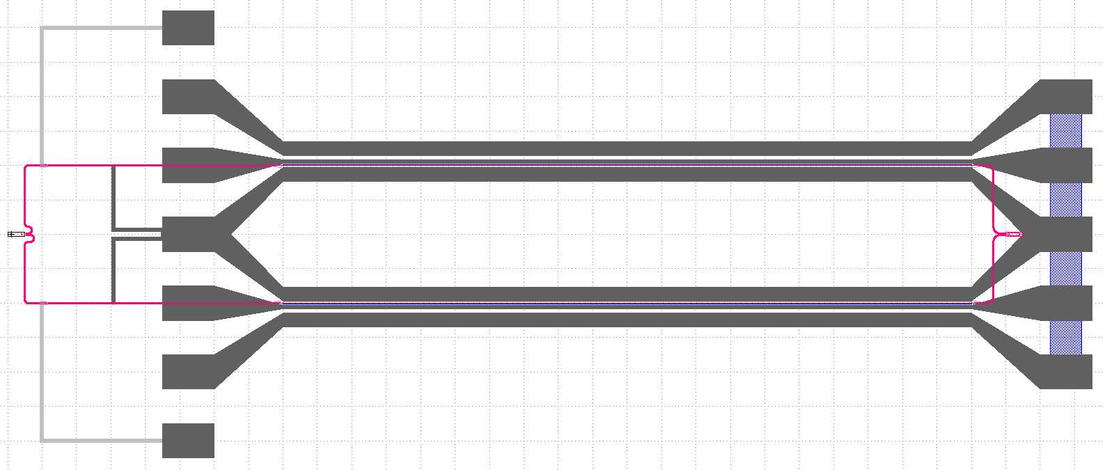
The modulator works in a differential push-pull configuration driven by a single GSGSG line with a contact pitch of rf_pitch, length rf_pad_length and width rf_pad_width.
The width of the signal lines is rf_signal_width, while the width of the ground lines is rf_ground_width.
The GSGSG lines are terminated by a load resistance resistance located at a distance given by resistance_spacing
after the end of the transmission line.
Reference
Click on the name of the component below to see the complete PCell reference.
Mach-Zehnder modulator with PN phase shifters in each arm. |
Examples
Example 1: instantiate an MZM and export the layout to GDSII.
from si_fab import all as pdk

# Phase Shifter
ps = pdk.PhaseShifterWaveguide(
    name="phaseshifter",
    length=1000.0,
    core_width=0.45,
    rib_width=7.8,
    junction_offset=-0.1,
    p_width=4.1,
    n_width=3.9,
)

# Heater
heater = pdk.HeatedWaveguide(name="heater")
heater.Layout(shape=[(0.0, 0.0), (100.0, 0.0)])

# Modulator
mzm = pdk.MZModulator(
    phaseshifter=ps,
    heater=heater,
    rf_pitch=100.0,
    rf_pad_length=75,
    rf_signal_width=5.0,
    rf_ground_width=20.0,
    heater_elpath_width=5.0,
)

mzm_lv = mzm.Layout()
mzm_lv.write_gdsii("mzm.gds")
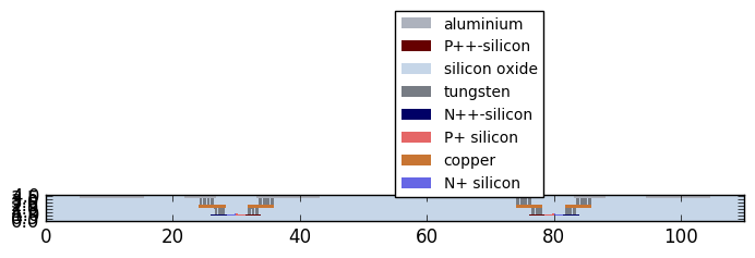
Example 2: plot the cross-section of the MZM.
from si_fab import all as pdk
from ipkiss3 import all as i3

# Phase Shifter
ps = pdk.PhaseShifterWaveguide(
    length=2.0,
    trace_template=pdk.RWG450(),
    junction_offset=-0.1,
)
# Modulator
mzm = pdk.MZModulator(
    phaseshifter=ps,
    spacing_x=40,
    rf_pitch=25.0,
    rf_pad_length=75,
    rf_signal_width=5.0,
    rf_ground_width=10.0,
    resistor_spacing=15.0,
    heater_elpath_width=5.0,
)


mzm_lv = mzm.Layout()
xs = mzm_lv.cross_section(cross_section_path=i3.Shape([(1.0, -35.0), (1.0, 35.0)]))  # Can be slow
fig = xs.visualize(show=False)
fig.savefig("mod_cross_section.png", bbox_inches="tight")
Model and simulation recipes
The circuit model of the MZM is a hierarchical model that is built on the individual models of the following components:
Phase shifter
Splitter
Taper
Heater
Waveguides
A simulation recipe is used to simulate the MZM, with a PRBS signal as a function of the following parameters:
cell: PCell of the MZM to simulate.mod_amplitude: Amplitude of the modulator.mod_noise: Amplitude of the noise on the modulator signal.opt_amplitude: Amplitude of the input signal.opt_noise: Amplitude of the noise at the optical input.v_heater1: Voltage over the first heater [V].v_heater2: Voltage over the second heater [V].bitrate: Bit rate of the signal.n_bytes: Number of bytes of the simulations.steps_per_bit: Number of time steps per bit.center_wavelength: Center wavelength of the optical carrier.debug: Debug mode.seed: Seed of the random number generation.
The test bench returns a dictionary of signals that can be used to do post-processing and plotting.
Reference
Click on the name of the function below to see the complete API reference of the simulation recipe.
|
Simulation recipe to simulate a Mach-Zehnder modulator using a PRBS signal. |
Example
from si_fab import all as pdk
from si_fab.components.modulator.mzm.simulation.simulate import simulate_modulation
import matplotlib.pyplot as plt
import numpy as np
import os
name = "simpler_simulation"
results_array = []
# Phase shifter
length = 1000.0
ps = pdk.PhaseShifterWaveguide(
name="phaseshifter",
length=length,
core_width=0.45,
rib_width=8.0,
junction_offset=-0.1,
)
vpi_lpi = 1.2 # V.cm
cl = 1.1e-15 # F/um
res = 50 # Ohm
tau = ps.length * cl * res
ps.CircuitModel(vpi_lpi=vpi_lpi)
# Heater
heater = pdk.HeatedWaveguide(name="heater")
heater.Layout(shape=[(0.0, 0.0), (100.0, 0.0)])
# Modulator
mzm = pdk.MZModulator(phaseshifter=ps, heater=heater)
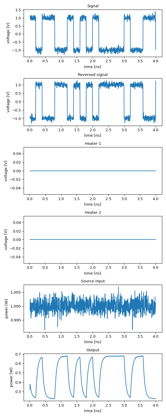
# Simulation
results = simulate_modulation(
cell=mzm,
mod_amplitude=1.0,
mod_noise=0.1,
opt_amplitude=1.0,
opt_noise=0.001,
v_heater_1=0.0,
v_heater_2=0.0,
bitrate=5e9,
n_bytes=20,
steps_per_bit=50,
center_wavelength=1.55,
debug=False,
seed=20,
)
def power(t):
return np.abs(t) ** 2
outputs = ["sig", "revsig", "h1", "h2", "src_in", "out"]
titles = ["Signal", "Reversed signal", "Heater 1", "Heater 2", "Source input", "Output"]
ylabels = ["voltage [V]", "voltage [V]", "voltage [V]", "voltage [V]", "power [W]", "power [W]"]
process = [np.real, np.real, np.real, np.real, power, power]
fig, axs = plt.subplots(nrows=len(outputs), ncols=1, figsize=(6, 15))
for ax, pr, out, title, ylabel in zip(axs, process, outputs, titles, ylabels):
data = pr(results[out][4:])
ax.set_title(title)
ax.plot(results.timesteps[4:] * 1e9, data, label=f"Length: {length}")
ax.set_xlabel("time [ns]")
ax.set_ylabel(ylabel)
plt.tight_layout()
fig.savefig(os.path.join(f"{name}.png"), bbox_inches="tight")
plt.show()
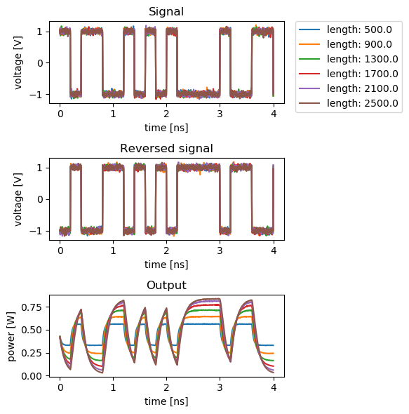
Sweeping the length of the phase shifter
In the following script the length of the phase shifter is swept to analyse the effect on the modulated signal. For short lengths, the modulation efficiency is dominated by the limited phase shift. For longer lengths it is limited by the RC constant of the device, due to the increased capacitance of the phase shifter.
from si_fab import all as pdk
from si_fab.components.modulator.mzm.simulation.simulate import simulate_modulation
import matplotlib.pyplot as plt
import numpy as np
import os

sweep_name = "sweep_length"

results_array = []
lengths = np.linspace(500, 2500, 6)

for lps in lengths:
    print(f"Simulating for length {lps} um")

    # Phase Shifter
    ps = pdk.PhaseShifterWaveguide(
        length=lps,
        core_width=0.45,
        rib_width=7.8,
        junction_offset=-0.1,
        n_width=3.9,
        p_width=4.1,
    )
    vpi_lpi = 1.2
    cl = 1.1e-15  # F/um
    res = 50
    tau = ps.length * cl * res
    ps.CircuitModel(vpi_lpi=vpi_lpi)

    # Modulator
    mzm = pdk.MZModulator(phaseshifter=ps)

    # Simulation
    results = simulate_modulation(
        cell=mzm,
        mod_amplitude=1.0,
        mod_noise=0.05,
        opt_amplitude=1.0,
        opt_noise=0.001,
        v_heater_1=0.0,
        v_heater_2=0.0,
        bitrate=5e9,
        n_bytes=20,
        steps_per_bit=50,
        center_wavelength=1.55,
        debug=False,
        seed=20,
    )
    results_array.append(results)


def power(t):
    return np.abs(t) ** 2


outputs = ["sig", "revsig", "out"]
titles = ["Signal", "Reversed signal", "Output"]
ylabels = ["voltage [V]", "voltage [V]", "power [W]"]
process = [np.real, np.real, power]
fig, axs = plt.subplots(nrows=3, ncols=1, figsize=(6, 6))

for ax, pr, out, title, ylabel in zip(axs, process, outputs, titles, ylabels):
    for length, results in zip(lengths, results_array):
        data = pr(results[out][1:])
        ax.set_title(title)
        ax.plot(results.timesteps[1:] * 1e9, data, label=f"length: {length}")
        ax.set_xlabel("time [ns]")
        ax.set_ylabel(ylabel)
        if ax is axs[0]:
            ax.legend(bbox_to_anchor=(1.05, 1), loc=2, borderaxespad=0.0)

plt.tight_layout()
fig.savefig(os.path.join(f"{sweep_name}.png"), bbox_inches="tight")
plt.show()
plt.close(fig)
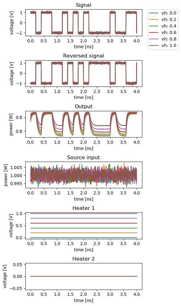
Sweeping the heater voltage
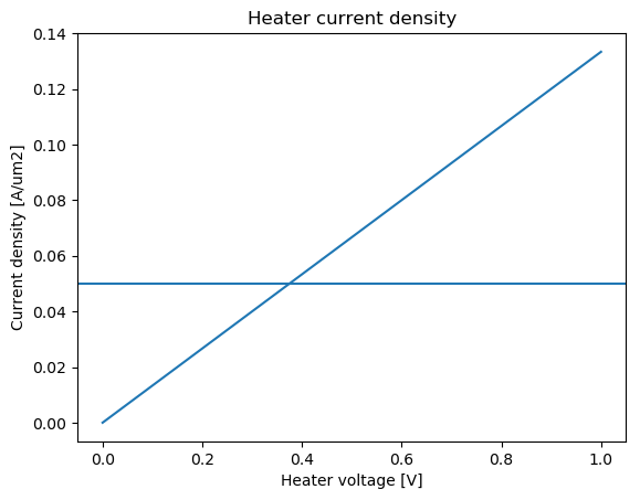
In the following script, the voltage applied on the heater is swept. By design, the modulation efficiency is at its maximum at 0 V. The modulation efficiency decreases as the heater voltage increases, while checking that the maximum current density is not exceeded.
from si_fab import all as pdk
from si_fab.components.modulator.mzm.simulation.simulate import simulate_modulation
from si_fab.components.heater.simulation.simulate import get_current_density
import matplotlib.pyplot as plt
import numpy as np
import os

sweep_name = "sweep_heater"

# Phase Shifter
ps = pdk.PhaseShifterWaveguide(
    name="phaseshifter",
    length=1000.0,
    core_width=0.45,
    rib_width=7.8,
    junction_offset=-0.1,
    n_width=3.9,
    p_width=4.1,
)
vpi_lpi = 1.2  # V.cm
Cl = 1.1e-15  # F/um
R = 50  # Ohm
j_max = 0.05  # A/um2 maximum current density assumption

tau = ps.length * Cl * R
ps.CircuitModel(vpi_lpi=vpi_lpi)

# Heater
heater = pdk.HeatedWaveguide(name="heater")
heater.Layout(shape=[(0.0, 0.0), (100.0, 0.0)])

# Modulator
mzm = pdk.MZModulator(phaseshifter=ps, heater=heater)

# Simulation
results_array = []
heater_voltages = np.linspace(0.0, 1.0, 6)

for v in heater_voltages:
    print(f"simulating for voltage {v:.1f}")
    results = simulate_modulation(
        cell=mzm,
        mod_amplitude=1.0,
        mod_noise=0.05,
        opt_amplitude=1.0,
        opt_noise=0.001,
        v_heater_1=v,
        v_heater_2=0,
        bitrate=5e9,
        n_bytes=20,
        steps_per_bit=50,
        center_wavelength=1.5,
        debug=False,
        seed=20,
    )
    results_array.append(results)


def power(t):
    return np.abs(t) ** 2


outputs = ["sig", "revsig", "out", "src_in", "h1", "h2"]
titles = ["Signal", "Reversed signal", "Output", "Source input", "Heater 1", "Heater 2"]
ylabels = ["voltage [V]", "voltage [V]", "power [W]", "power [W]", "voltage [V]", "voltage [V]"]
process = [np.real, np.real, power, power, np.real, np.real]
fig, axs = plt.subplots(nrows=6, ncols=1, figsize=(6, 10))

for ax, pr, out, title, ylabel in zip(axs, process, outputs, titles, ylabels):
    for v, results in zip(heater_voltages, results_array):
        data = pr(results[out][1:])
        ax.set_title(title)
        ax.plot(results.timesteps[1:] * 1e9, data, label=f"vh: {v:.1f}")
        ax.set_xlabel("time [ns]")
        ax.set_ylabel(ylabel)
        if ax is axs[0]:
            ax.legend(bbox_to_anchor=(1.05, 1), loc=2, borderaxespad=0.0)

plt.tight_layout()
fig.savefig(os.path.join(f"{sweep_name}.png"), bbox_inches="tight")
plt.show()

fig = plt.figure()
plt.plot(heater_voltages, get_current_density(cell=heater, v_bias=heater_voltages), label="Current density")
plt.title("Heater current density")
plt.xlabel("Heater voltage [V]")
plt.ylabel("Current density [A/um2]")
plt.axhline(y=j_max, label="Maximum current density")
fig.savefig(os.path.join("{}.png".format("current_density")), bbox_inches="tight")
plt.show()