4. Mach-Zehnder modulator (MZM)
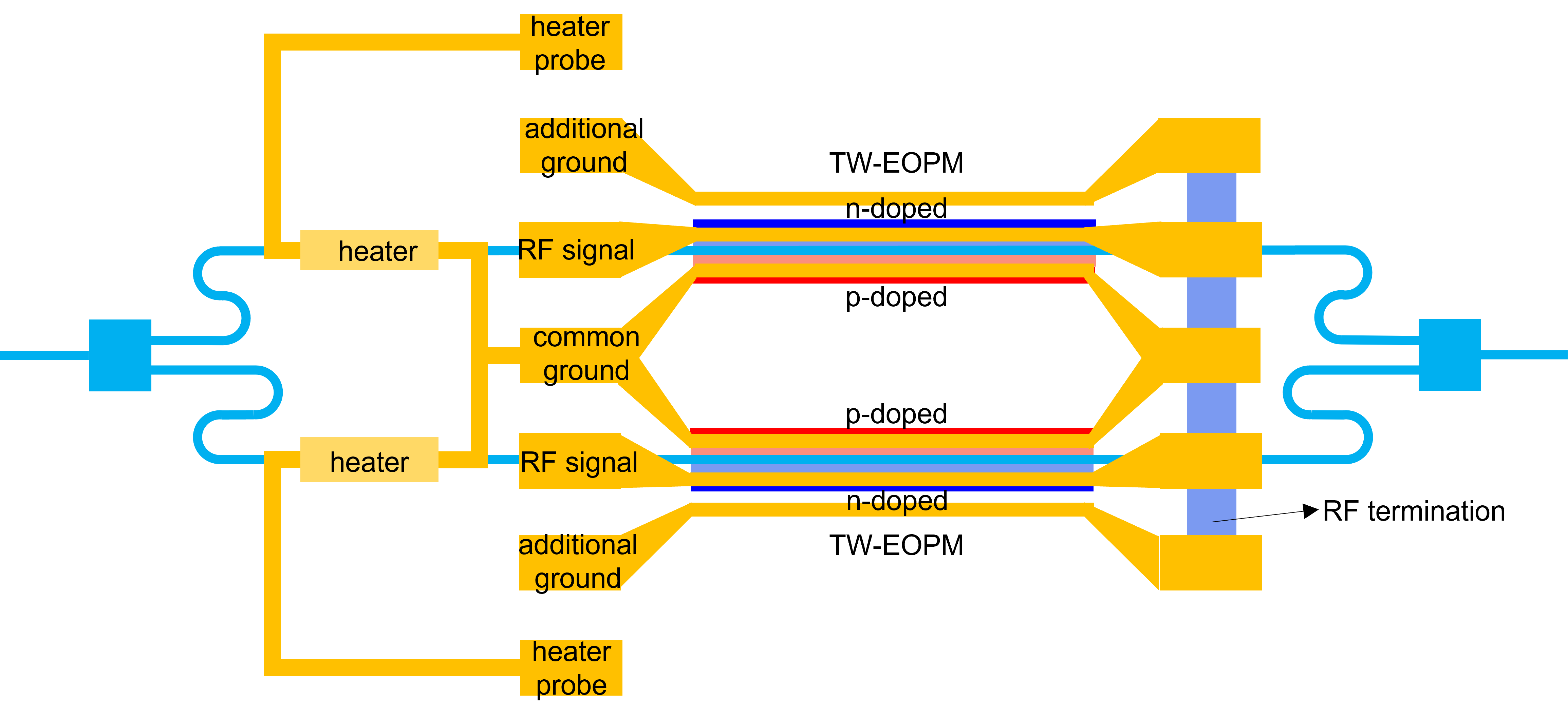
As explained in the introduction, a Mach-Zehnder modulator is based on a Mach-Zehnder interferometer (MZI), which splits the light in two branches and then recombines them by interference. In each branch, a heater-based phase shifter is placed to ensure the MZM is biased at quadrature. A carrier depletion based travelling wave electro-optic phase modulator (TW-EOPM) is also placed in each branch for the high-speed modulation and to allow for push-pull operation. The heater-based phase shifters are thus used to optimize the modulation efficiency, regardless of the high-speed voltage signal and its DC offset applied to the TW-EOPMs.
The MZM in this example has thus the same topology as the last picture in the introduction. What wasn’t covered was how exactly the metal on the modulators are connected electrically. In this example, we assume that both the heaters as well as the TW-EOPMs have a common ground. The signal lines are separate, of course, and additional ground lines are added along the TW-EOPMs as it will improve the RF signal degradation. These RF lines are then all terminated with a resistor, in order to avoid RF reflections at the end of the TW-EOPMs, as these reflections will degrade the performance of the TW-EOPMs. Finally, since the heaters are connected to the common ground, we need to add two extra pads for injecting them with a current. As such, the topology of our MZM becomes:

4.1. Layout
The layout of the MZM is mainly described by the properties of its sub-components, which are the two TW-EOPMs, the heaters and the tapers that connect the regular waveguide with the active, doped, waveguides of the TW-EOPMs.
In addition, some other properties control how the modulator is connected electrically:
rf_pitchrf_pad_lengthrf_pad_widthrf_signal_widthrf_ground_width
As mentioned in the introduction, the top and bottom arms have unequal lengths in order to have the MZM operate at quadrature (or phase difference of \(\pi/2\)) where the modulation efficiency is optimized, without the need for DC biasing.
But as also mentioned, fabrication errors will naturally induce additional asymmetries, which is why we need additional heaters to compensate for these parasitic effects.
Nevertheless, this still begs the question: how do we achieve this required length difference at the operating wavelength center_wavelength?
Well, this length difference between the two arms is obtained directly from the waveguide model at center_wavelength.
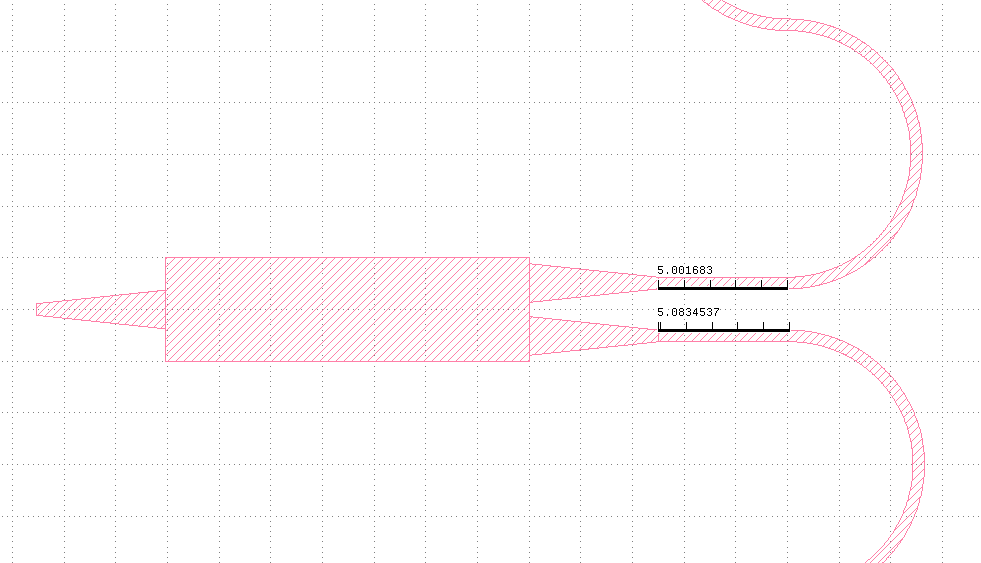
The MZM cell automatically calculates this parameter and is implemented in the layout class of the MZM using a small U-bend in the waveguide.
This is illustrated below:

4.2. Model and simulation recipes
The circuit model of the MZM is a hierarchical model that is built on the individual models of the following components:
TW-EOPM
Splitter
Taper
Heater
Waveguides
The simulation recipes can be used to simulate the modulator, check the modulation efficiency and explore different compromises that can be made when designing this component.
Check out the following examples:
4.3. Test your knowledge
Exercise 1: Explore the design parameters
Copy
si_fab/ipkiss/si_fab/components/modulator/mzm/doc/example_mzm_layout.py.Explore the parameter space provided and inspect the GDS layout in KLayout.
Check the unbalance of the two arms.
Exercise 2 - Modulation efficiency: varying the length of the phase shifter
Copy
si_fab/ipkiss/si_fab/components/modulator/mzm/doc/example_mzm_sweep_length.py.What is the maximum extinction ratio you can obtain with a PRBS signal at 5 Gbit/s?
Add noise to the modulation signal and check the effect.
Add noise to optical signal and check the effect.
Exercise 3 - Tuning: varying the heater length and voltage
Copy
si_fab/ipkiss/si_fab/components/modulator/mzm/doc/example_mzm_sweep_heater.py.Change the metal width of the heater. What is the effect?
Change the length of the heater. What is the effect?