3. Thermo-optic phase shifter (Heater)
In this section, we will discuss how to implement the layout and the circuit model of the heater-based phase shifter. The operation principle of the heater is fairly straightforward. A resistive material is placed above (or near) and along the waveguide. In SiFab, this resistive material is titanium nitride. Injecting a current through that material will heat it up and consequently will also heat up the surrounding area, including the waveguide. This change in temperature will change the refractive index of the waveguide material through the thermo-optic effect. This, in turn, modulates the effective index and the phase of the light at the end of the waveguide.
We will now look at how to properly layout the heaters so that, when we have them fabricated in the foundry, they will operate properly.
3.1. Layout
The heater element in SiFab is simply a waveguide with two heaters in close proximity to it (in order to have equal temperature change on both sides of the waveguide) that follow the same trace as the waveguide. At the start and end of the heater section, there are two metal contact pads for external probing. This component is part of the SiFab PDK, namely heater, and it is used in this application example.
An example of a straight heater waveguide is shown in the following figures:
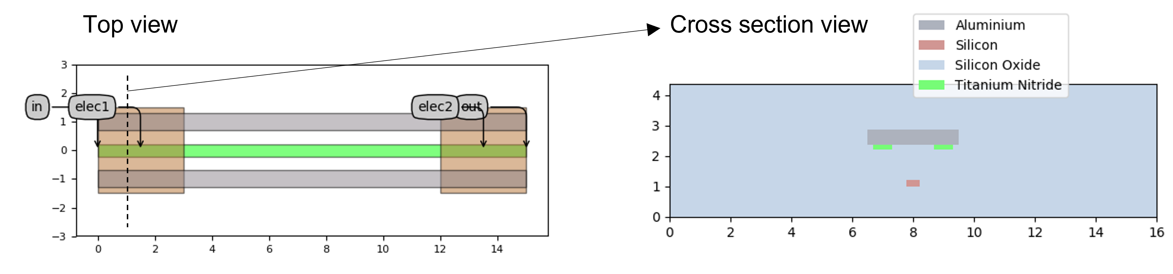
Top view (left) and cross-section view (right) of the heater waveguide, consisting of an optical waveguide and two parallel heaters placed on both sides of the optical waveguide. There are electric pads at the start and end of the heater waveguide.
It should be stressed that considering the heated waveguide can be used as any other waveguide in IPKISS, you can make any heater waveguide traces you want. An example is routing the heater waveguide along a ring shape as shown below, although more complex traces can be realised:
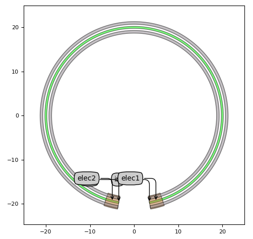
Top view of a circular heater waveguide
The code for creating the straight and ring shaped heater waveguides is given below for reference:
import si_fab.all as pdk
from ipkiss3 import all as i3

# Heater with straight shape
ht_straight = pdk.HeatedWaveguide(
    heater_width=0.6,
    heater_offset=1.0,
    m1_extension=0.2,
    m1_length=3.0,
)
ht_straight_lv = ht_straight.Layout(shape=[(0.0, 0.0), (15.0, 0.0)])
ht_straight_lv.visualize(annotate=True)

xs = ht_straight_lv.cross_section(cross_section_path=i3.Shape([(1.0, -8.0), (1.0, 8.0)]))
xs.visualize()

# Heater with circular shape
ht_circ = pdk.HeatedWaveguide()
ht_circ_lv = ht_circ.Layout(
    shape=i3.ShapeArc(radius=20.0, start_angle=280, end_angle=260),
)
ht_circ_lv.visualize(annotate=True)
3.2. Model
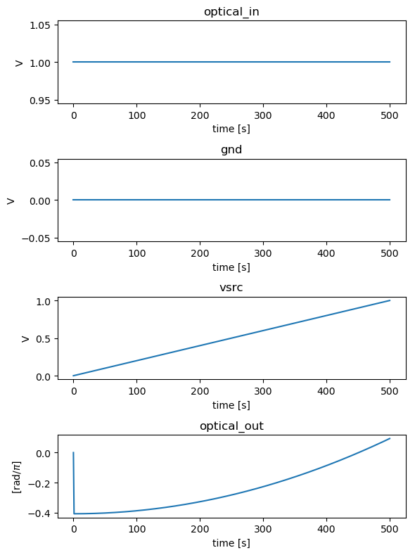
As described in the SiFab documentation of the heater, the phase shift is proportional to the dissipated power in the heater. As the dynamics controlling the temperature are much slower than the electro-optic effects in the phase shifter, we chose an instantaneous model. By doing so, we can reach steady-state immediately.
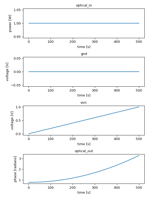
The heater in SiFab has a simulation recipe, which is used to ramp up the voltage and check the phase variation. Below we show the code to instantiate a 100 um-long heater waveguide and how to employ the simulation recipe to check out this component. We also provide the simulation results.
import si_fab.all as pdk
from si_fab.components.heater.simulation.simulate import simulate_heater
from si_fab.components.heater.pcell.cell import r_sheet
import matplotlib.pyplot as plt
import numpy as np
import os

# Phase Shifter
name = "heater_sweep"
length = 100
ht = pdk.HeatedWaveguide(
    heater_width=0.6,
    heater_offset=1.0,
    m1_extension=0.2,
    m1_length=3.0,
)
ht_lv = ht.Layout(shape=[(0.0, 0.0), (length, 0.0)])

# Power for pi phase shift per square of unit sheet resistance
p_pi = 30e-3  # W
p_pi_sq = r_sheet * p_pi
ht.CircuitModel(p_pi_sq=p_pi_sq)

results = simulate_heater(
    cell=ht,
    v_start=0,
    v_end=1,
    nsteps=500,
    center_wavelength=1.5,
    debug=False,
)
times = results.timesteps


def phase_unwrap_normalize(transmission):
    unwrapped = np.unwrap(np.angle(transmission))
    return unwrapped - unwrapped[0]


signals = ["optical_in", "gnd", "vsrc", "optical_out"]
process = [np.real, np.real, np.real, phase_unwrap_normalize]
ylabels = ["power [W]", "voltage [V]", "voltage [V]", "phase [radians]"]

fig, axs = plt.subplots(nrows=len(signals), ncols=1, figsize=(6, 8))
for axes, process, signal, ylabel in zip(axs, process, signals, ylabels):
    data = process(results[signal])
    axes.set_title(signal)
    axes.plot(times[1:], data[1:])
    axes.set_ylabel(ylabel)
    axes.set_xlabel("time [s]")
plt.tight_layout()
fig.savefig(os.path.join(f"{name}.png"), bbox_inches="tight")
plt.show()
plt.close(fig)
3.3. Test your knowledge
Exercise 1
Open
topical_training/mzm/explore_heater/example_heated_waveguide.py.Play with the properties and try to understand their meaning.
Exercise 2
Open
topical_training/mzm/explore_heater/example_heater_simulation.py.Play with the parameters of the heater - length, width, applied voltage.
With the heater having a \(P_{\pi}=\) 30 mW, find the the length of the heater that would lead to a tuning range of \(\pi/2\) under a voltage swing of 0 to 1.