Controlling the waveguides length
It is useful to be able to control the shape of the right arm of the MZI by changing the position of the control point. However, it is not an efficient way to control the length of this arm. Because the MZI is an interferometric structure, having good control over the length difference (called delay length) between the left and right arms is very important.
Function to control the delay length
Let’s see how to define a function in IPKISS, using Python code, that allows us to automatically extract the coordinates of the control point based on the desired delay length we want to achieve.
def define_control_point(delay_length, bend_radius, control_point_y):
    """Defines a control point based on the desired delay_length"""

    def f(x):
        device = MZI(
            control_point=(x[0], control_point_y),
            bend_radius=bend_radius,
        )
        right_arm_length = device.get_connector_instances()[1].reference.trace_length()
        left_arm_length = device.get_connector_instances()[0].reference.trace_length()
        current_delay_length = right_arm_length - left_arm_length
        cost = current_delay_length - delay_length
        return np.abs(cost)

    from scipy.optimize import minimize

    control_point_x = minimize(f, x0=np.array(70.0), tol=1e-2, bounds=((45.0, 200.0),)).x[0]
    return control_point_x, control_point_y
Let’s have a detailed look at the code:
We provide three arguments to the function: the desired delay length between the two MZI arms, the bend radius to be used for the waveguides (it affects the waveguide length) and the y-coordinate of the control point. The function will take care of finding the x-coordinate that satisfies these conditions.
Inside this function, we define another function f(x) that returns the value we want to minimize. In this case, we instantiate an MZI, calculate the length difference between the two arms and compare this value with the desired delay length. The difference between these two values is the value we want to minimize (cost). When the difference approaches zero then we have obtained the delay length we wanted.
Next, we use the
minimizemethod from SciPy (Python scientific library) to find the valuex, which in our case is the x-coordinate of the control point, that allows us to minimize the function f(x). In other words, we want to find the x-coordinate that corresponds to the desired delay length, given the desired bend radius. We provide an initial guess for the value x, which is x0. We also provide bounds, so that the waveguide arm doesn’t intersect with the rest of the circuit.
Design variations controlling the delay length
Using the define_control_point function, we can now create design variations controlling the delay length.
The code is very similar to that which you’ve used in the previous section but, instead of providing a list of control points as the parameter for the MZI sweep, we provide a list of delay lengths.
When using a for-loop to create the MZI sweep, we iterate over the values contained in delay_lengths.
We first use the define_control_point function to extract the coordinates of the control point that corresponds to that delay length and then use this information to instantiate the MZI.
# Create the MZI sweep
for ind, delay_length in enumerate(delay_lengths):
    cp = define_control_point(
        delay_length=delay_length,
        bend_radius=bend_radius,
        control_point_y=240.0,
    )

    # Instantiate the MZI
    mzi = MZI(
        name=f"MZI{ind}",
        control_point=cp,
        bend_radius=bend_radius,
    )

    # Calculate the actual delay length and print the results
    right_arm_length = mzi.get_connector_instances()[1].reference.trace_length()
    left_arm_length = mzi.get_connector_instances()[0].reference.trace_length()
    actual_delay_length = right_arm_length - left_arm_length

    print(
        mzi.name,
        f"Desired delay length = {delay_length} um",
        f"Actual delay length = {actual_delay_length} um",
        f"Control point = {cp}",
    )

    # Add the MZI to the instances dict and place it
    mzi_cell_name = f"mzi{ind}"
    insts[mzi_cell_name] = mzi
    specs.append(i3.Place(mzi_cell_name, (x0, y0)))

    x0 += spacing_x
You can see that, in the for-loop, we added a print statement that prints the value of delay length with the associated coordinate of the control point. Next time you want to create and simulate this circuit, you don’t need to run the minimization algorithm anymore. You can use the code from the previous section, provide the coordinates of the control points, and you will already know to what delay lengths they correspond.
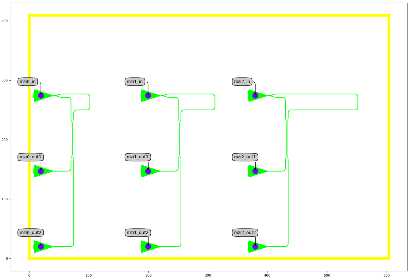
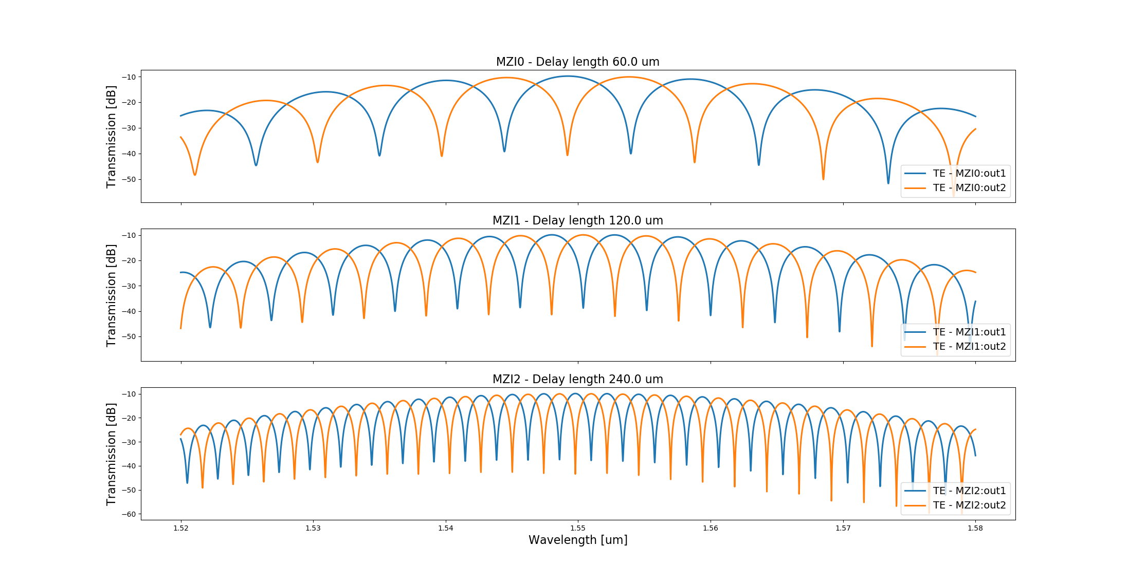
Layout and circuit simulation
Below are the layout and circuit simulation for delay_lengths=[(60.0, 120.0, 240.0)] and bend_radius=5.0.
Test your knowledge
The way we have defined the function to relate a delay length to the coordinate of a control point only accounts for the existence of one control point. If you would like to create more complex routes, or if the delay length you would like to use makes your right MZI arm very long, you may consider using more than one control point.
As an exercise, you may try to write a function with which you can use more than one control point.
Don’t forget to adapt the control_point property of the MZI PCell as well, so that it accepts a list.