Note
Go to the end to download the full example code
Exporting a 3D Model file
This example shows how to export a Wavefront OBJ file that can be loaded in many 3D CAD tools.
We use the write_obj method of
i3.device_sim.SimulationGeometry.
This method will write an OBJ file .obj together with a .mtl materials file.
We start by creating an example circuit based on the si_fab example PDK: a Mach-Zehnder in silicon nitride waveguides, with a thermo-optic phase tuner in one of the arms. The heater is connected to bondpads.
import si_fab.all as pdk  # noqa
import ipkiss3.all as i3

# basic parameters, waveguide and metal trace templats
heater_length = 100.0
bend_radius = 40.0
trace_template = pdk.NWG900()
metal_trace_template = pdk.M1WireTemplate()
metal_trace_template.Layout(width=3)

# subcells
dc = pdk.SiNDirectionalCouplerSPower(power_fraction=0.5, target_wavelength=1.55)
heated_waveguide = pdk.HeatedWaveguide(trace_template=trace_template)
heated_waveguide.Layout(shape=[(0.0, 0.0), (heater_length, 0.0)])
waveguide = i3.Waveguide(trace_template=trace_template)
waveguide.Layout(shape=[(0.0, 0.0), (heater_length, 0.0)])
bondpad = pdk.BONDPAD_5050()

# MZI connected to bondpads
mzi = i3.Circuit(
    name="tuneable_mzi",
    insts={
        "dc1": dc,
        "dc2": dc,
        "ht": heated_waveguide,
        "wg": waveguide,
        "bp1": bondpad,
        "bp2": bondpad,
    },
    specs=[
        i3.Place("dc1:in1", (0.0, 0.0)),
        i3.Place("ht:in", (80.0, 40.0), relative_to="dc1:out2"),
        i3.Place("wg:in", (80.0, -40.0), relative_to="dc1:out1"),
        i3.Place("dc2:in2", (80.0, -40.0), relative_to="ht:out"),
        i3.Place("bp1", (-50.0, 50.0), relative_to="ht@NW"),
        i3.Place("bp2", (50.0, 50.0), relative_to="ht@NE"),
        i3.ConnectBend("dc1:out2", "ht:in", bend_radius=bend_radius),
        i3.ConnectBend("dc1:out1", "wg:in", bend_radius=bend_radius),
        i3.ConnectBend("ht:out", "dc2:in2", bend_radius=bend_radius),
        i3.ConnectBend("wg:out", "dc2:in1", bend_radius=bend_radius),
        i3.ConnectElectrical(
            "ht:elec1",
            "bp1:m1",
            start_angle=90.0,
            end_angle=0.0,
            trace_template=metal_trace_template,
        ),
        i3.ConnectElectrical(
            "ht:elec2",
            "bp2:m1",
            start_angle=90.0,
            end_angle=180.0,
            trace_template=metal_trace_template,
        ),
    ],
    exposed_ports={
        "dc1:in1": "in1",
        "dc1:in2": "in2",
        "dc2:out1": "out1",
        "dc2:out2": "out2",
        "bp1:m2": "ht1",
        "bp2:m2": "ht2",
    },
)

mzi_layout = mzi.Layout()
We can first inspect the layout to check if everything is correct
mzi_layout.visualize(annotate=True)
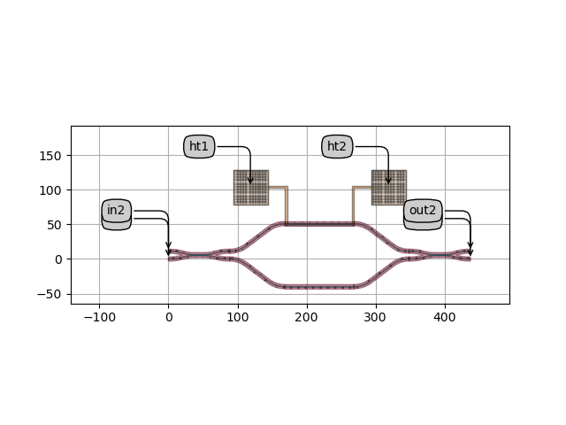
Exporting a 3D model from this layout is done in two steps:
First, we create a SimulationGeometry with the given layout. A virtual fabrication process flow to use can be specified.
Secondly, we call its
write_objmethod to export an OBJ file and associated MTL file.
mzi_geometry = i3.device_sim.SimulationGeometry(
    layout=mzi_layout,
    process_flow=i3.TECH.VFABRICATION.PROCESS_FLOW,
)
mzi_geometry.write_obj(filename="tuneable_mzi.obj")
This OBJ file can now be loaded in many 3D CAD tools Several on-line viewers exist as well as tools for 3D modeling, 3D printing, mechanical and thermal simulation, and so forth. For the example, we’ve installed the open source Mayo tool. After dragging and dropping the OBJ file on the tool window, you can inspect the 3D geometry:
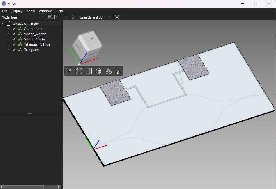
3D Model loaded in Mayo
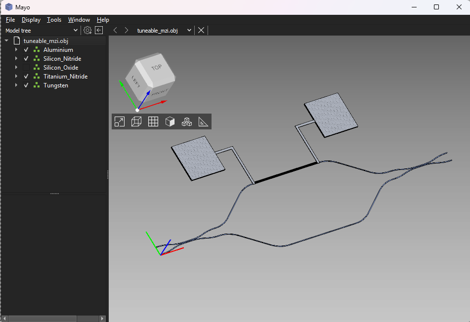
We can choose to only visualize the materials we want, e.g. disabling the oxide layers:

3D Model loaded in Mayo, with oxide material disabled
And we can inspect different parts of the geometry, using rotation (left mouse), panning (right mouse) and zooming (both mouse buttons or wheel):
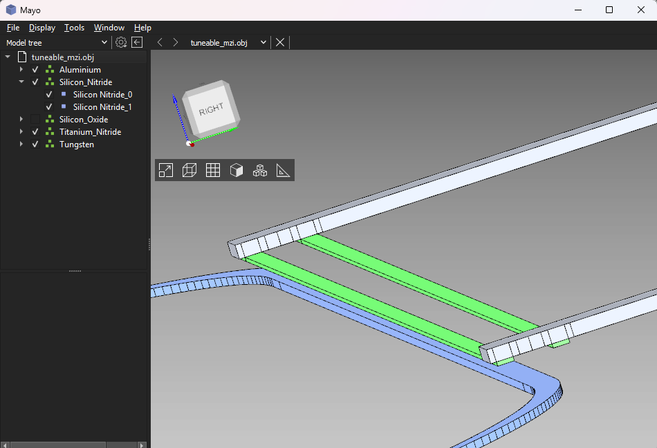
Zoom on the heater section and contact
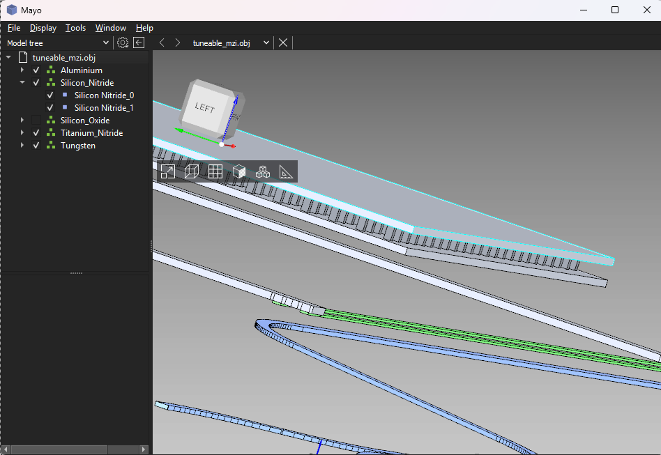
Zoom on the heater section and bondpad
An alternative to the OBJ file format is STL (which is often used for single material 3D printing)
This can be exported in the same fashion using the
write_stl method instead.
STL files do not support materials, so one STL file per material is exported by default.