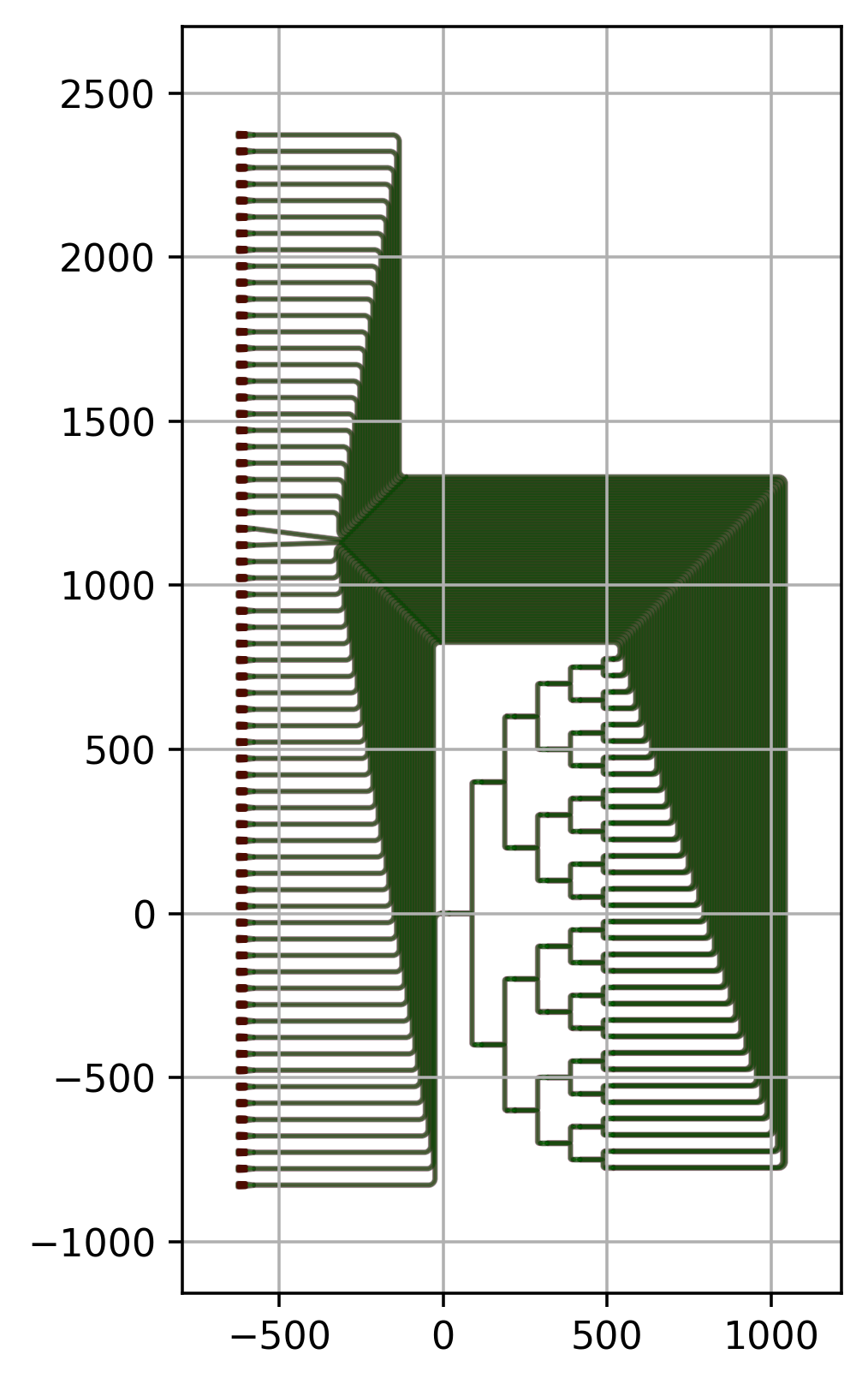
Routing to the Chip Edge
Introduction
Connecting components is an important part of every integrated photonics design.
In Designing a splitter tree, an introduction is given on how to connect two ports with each other using a single connector.
This is usually provided in the context of the placement and routing of instances using i3.place_and_route (or i3.Circuit, which internally calls i3.place_and_route):
specs = [
    i3.ConnectBend(
        [
            ("sp_0_0:out1", "sp_1_0:in1"),
            ("sp_0_0:out2", "sp_1_1:in1")
        ],
        adiabatic_angles=(1.0, 1.0),
    )
]
The list of connectors offers an overview of what is connected and how. We recommend that for any circuit you make, whether simple or complex, you use a list of routing specifications as it provides a clear overview of your intended connections and a way to customize them.
As documented in Designing a splitter tree, a list of ready-made connectors is provided that you can use to connect your components with each other. This approach is usually enough for simple connections that don’t need to be customized beyond the parameters of the connector function. Before we get into more complicated examples, let’s warm up with a simple example using simple connectors.
Warm-up
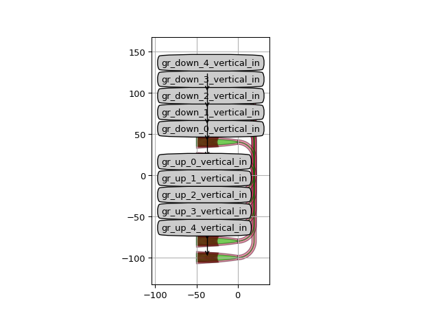
Start from the skeleton exercise.py, where all the waveguides overlap.
from si_fab import all as pdk
from ipkiss3 import all as i3
import numpy as np


grating = pdk.FC_TE_1550()
spacings = np.linspace(0, 10, 5)
insts = dict()

bend_radius = 20.0
spacing = 5.0
spacing_x = 0 * bend_radius
spacing_y = 2 * bend_radius
specs = []

for cnt, sp in enumerate(spacings):
    gr_up = f"gr_up_{cnt}"
    gr_down = f"gr_down_{cnt}"
    gr_up_port = f"{gr_up}:out"
    gr_down_port = f"{gr_down}:out"
    insts[gr_up] = grating
    insts[gr_down] = grating
    specs.append(i3.Place(gr_up_port, (spacing_x, (-cnt / 2.0 - 0.5) * spacing_y)))
    specs.append(i3.Place(gr_down_port, (0, (cnt / 2.0 + 0.5) * spacing_y)))
    connector = i3.ConnectManhattan(
        gr_up_port,
        gr_down_port,
        min_straight=0.0,
        control_points=[(i3.V(i3.START + bend_radius))],
        bend_radius=bend_radius,
    )
    specs.append(connector)


cell = i3.Circuit(
    insts=insts,
    specs=specs,
)
cell.Layout().visualize(annotate=True)
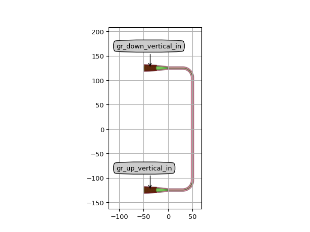
In some cases, we’d want to have the control points for manhattan routes. For that purpose we can use control points. For example, we can specify that the connection should go through a vertical line at 50um.:
from si_fab import all as pdk
from ipkiss3 import all as i3

grating = pdk.FC_TE_1550()
fiber_spacing = 250.0
bend_radius = 20.0

cell = i3.Circuit(
    insts={
        "gr_up": grating,
        "gr_down": grating,
    },
    specs=[
        i3.Place("gr_up:out", (0.0, -0.5 * fiber_spacing)),
        i3.Place("gr_down:out", (0.0, 0.5 * fiber_spacing)),
        i3.ConnectManhattan(
            "gr_down:out",
            "gr_up:out",
            min_straight=0.0,
            bend_radius=bend_radius,
            control_points=[i3.V(50.0)],
        ),
    ],
)

cell.Layout().visualize(annotate=True)
Alternatively, we can move the route as closely as possible next the the grating couplers using a relative control points.
from si_fab import all as pdk
from ipkiss3 import all as i3

grating = pdk.FC_TE_1550()
fiber_spacing = 250.0
bend_radius = 20.0

cell = i3.Circuit(
    insts={
        "gr_up": grating,
        "gr_down": grating,
    },
    specs=[
        i3.Place("gr_up:out", (-100.0, -0.5 * fiber_spacing)),
        i3.Place("gr_down:out", (-100.0, 0.5 * fiber_spacing)),
        i3.ConnectManhattan(
            "gr_down:out",
            "gr_up:out",
            min_straight=0.0,
            bend_radius=bend_radius,
            control_points=[i3.V(i3.START + bend_radius)],
        ),
    ],
)

cell.Layout().visualize(annotate=True)
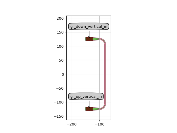
The available anchors for relative control points are i3.START (the start port), i3.END (the end port) and
i3.PREV (the previous control point in a list of multiple control points).
Now, try to fix this design to obtain the following layout of a grating array:
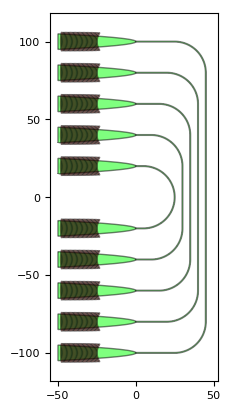
Routing to the chip edge
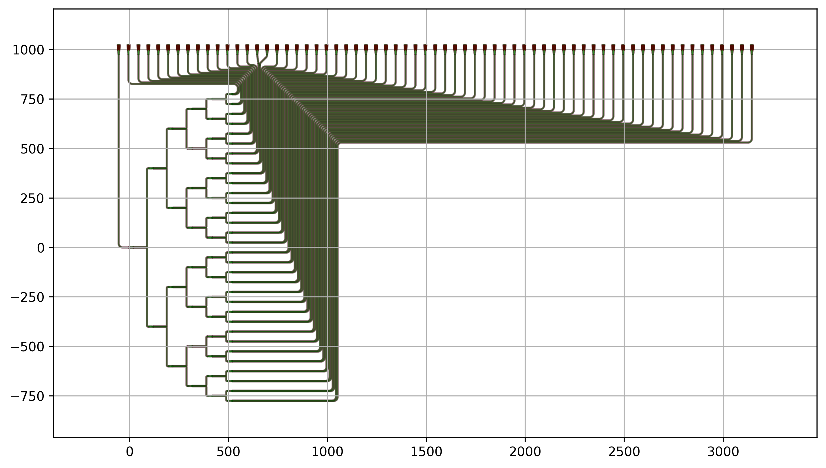
An image tells more than a thousand words. Let’s have a look at the following routed splitter tree.
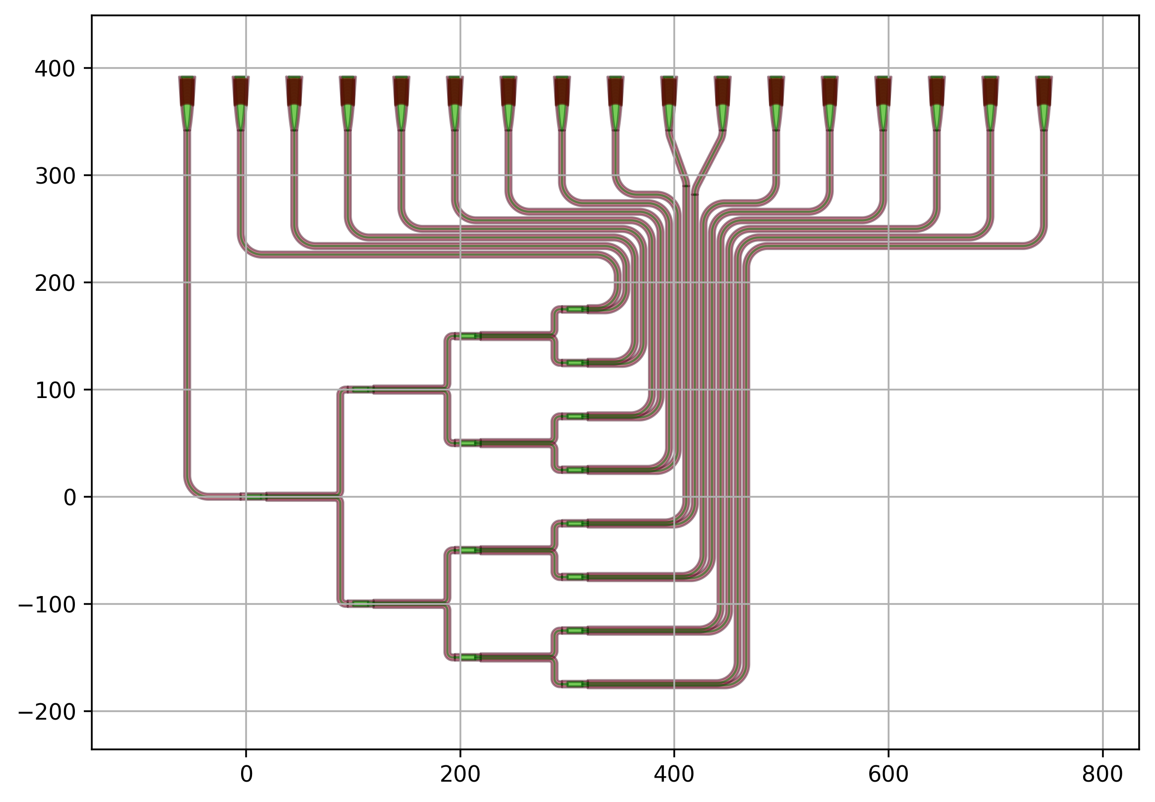
A careful look at the waveguides in this design shows that although they are all part of the same bundle, their paths strongly vary. Some waveguides:
Just have one bend (input waveguide)
Route around the corner and go up (gratings to the left)
Route up and have an S-bend at the end (gratings in the middle)
Route up and to the right (gratings to the right)
Which approach to take depends on the relative positioning of the grating to the output port of the splitter tree. While Luceda IPKISS does not have full autorouting capability, it is a very convenient platform to use code to implement a routing heuristic for your circuits that accommodates parametric changes to your device-under-test (splitter tree in this example).
Taking the time to code a routing heuristic has the following advantages:
Heuristics translate well from one design to the next.
A routing heuristic can be improved step-by-step.
A routing heuristic is fully customizable.
A routing heuristic saves you a lot of work when making small changes to your device-under-test.
In this tutorial we will use examples introduce the coding practices used in the routed splitter tree.
Chaining Connectors
In the example above we have connectors that use a Manhattan route in the first portion and switch to an S-bend in the second portion. This is the case for the waveguides that are routed to the gratings in the middle. To build a chain of combined connectors, one needs to instantiate them based on already placed components and route each of them to/from an intermediate port place at the specified connection point.
Let’s have a look at the following example. Two grating couplers are connected using an S-bend from the first grating (gc1) up to (100, 100) and a manhattan routing from (100, 100) to the second grating (gc2).
from si_fab import all as pdk
from ipkiss3 import all as i3

gr = pdk.FC_TE_1550()
intermediate_port = i3.OpticalPort(name="intermediate", position=(100, 100), angle=180)
bend_radius = 5
circuit = i3.Circuit(
    insts={"gc1": gr, "gc2": gr},
    specs=[
        i3.Place("gc1:out", (0, 0)),
        i3.Place("gc2:out", (200, 200)),
        i3.FlipH("gc2"),
        i3.ConnectBend(
            "gc1:out",
            intermediate_port,
            "connect_bend_from_gc1_out",
            bend_radius=bend_radius,
        ),
        i3.ConnectManhattan(
            intermediate_port.flip_copy(),
            "gc2:out",
            "connect_manhattan_from_gc2_out",
            bend_radius=bend_radius,
        ),
    ],
)
circuit_layout = circuit.Layout()
circuit_layout.visualize()
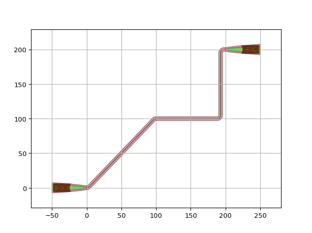
luceda-academy/training/topical_training/routing_chip_edge/example_combine_connector1.py
In this example, we first define an intermediate_port which will be the point where the connectors will combine. Don’t forget to name the intermediate port.
The name of the connector and the bend_radius are specified for all the subsections of the connector chain as a part of specs.
Sometimes, it is required to set the properties of the connectors at an individual level. This can be done by passing additional arguments to the connectors before combining them. This is demonstrated in the example below in which a control point is added to the manhattan section.
from si_fab import all as pdk
from ipkiss3 import all as i3

gr = pdk.FC_TE_1550()
intermediate_port = i3.OpticalPort(name="intermediate", position=(100, 100), angle=180)
bend_radius = 5
circuit = i3.Circuit(
    insts={"gc1": gr, "gc2": gr},
    specs=[
        i3.Place("gc1:out", (0, 0)),
        i3.Place("gc2:out", (200, 200)),
        i3.FlipH("gc2"),
        i3.ConnectBend("gc1:out", intermediate_port, "connect_bend_from_gc1_out", bend_radius=bend_radius),
        i3.ConnectManhattan(
            intermediate_port.flip_copy(),
            "gc2:out",
            "connect_manhattan_from_gc2_out",
            control_points=[i3.V(150), i3.H(150)],
            bend_radius=bend_radius,
        ),
    ],
)
circuit_layout = circuit.Layout()
circuit_layout.visualize()
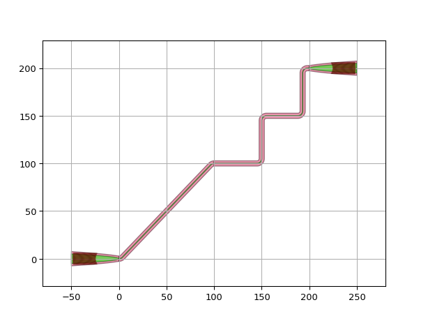
luceda-academy/training/topical_training/routing_chip_edge/example_combine_connector2.py
Bundles
In the routed splitter tree example we have bundles of waveguides that are packed together with a specific waveguide separation. The best way to handle this is to use conditional waypoints that are shifted left or right (and up or down) depending on their relative position in the bundle. In addition, we use conditional connectors, where the routing methodology is adapted depending on the relative position of the waveguide in the bundle. In the example below we have:
two conditional waypoints, wp1 and wp2;
two options for the conditional connector:
when the y-coordinate of the waveguide (wp_y) is almost at the same height as the grating coupler, an S-bend is used in the first and the last part of the connector;
when the y_coordinate of the waveguide (wp_y) is above or below the grating coupler, then a manhattan connector is used from start to finish.
from si_fab import all as pdk
from ipkiss3 import all as i3
import numpy as np

gr = pdk.FC_TE_1550()
insts = {}
specs = []
sep = 28.0
wav_sep = 5.0
bend_radius = 5.0
wp1x = 50.0
wp2x = 350.0
wp_y = 55.0

for cnt in range(10):
    gc_in = f"gc_in{cnt}"
    gc_out = f"gc_out{cnt}"
    gr_y = cnt * sep
    insts[gc_in] = gr
    insts[gc_out] = gr

    specs.extend(
        [
            i3.Place(gc_in + ":out", (0, gr_y)),
            i3.Place(gc_out + ":out", (400, gr_y)),
            i3.FlipH(gc_out),
        ]
    )

    # Controlling the conditional waypoints
    wp_y += wav_sep
    if wp_y > gr_y:
        wp1x -= wav_sep
        wp2x += wav_sep
    else:
        wp1x += wav_sep
        wp2x -= wav_sep

    # Controlling the conditional routing specifications
    if np.abs(wp_y - gr_y) > 2 * bend_radius:
        specs.append(
            i3.ConnectManhattan(
                gc_in + ":out",
                gc_out + ":out",
                control_points=[i3.V(wp1x), i3.H(wp_y), i3.V(wp2x)],
                bend_radius=bend_radius,
                min_straight=0.0,
            )
        )
    else:
        intermediate_port1 = i3.OpticalPort(name="intermediate_port1", position=(wp1x, wp_y), angle=180)
        intermediate_port2 = i3.OpticalPort(name="intermediate_port2", position=(wp2x, wp_y), angle=180)
        specs.extend(
            [
                i3.ConnectBend(
                    gc_in + ":out",
                    intermediate_port1,
                    f"connect_gc_in_{cnt}",
                    bend_radius=bend_radius,
                    start_straight=0.0,
                    end_straight=0.0,
                ),
                i3.ConnectManhattan(
                    intermediate_port1.flip_copy(),
                    intermediate_port2,
                    f"connect_gc_mid_{cnt}",
                    bend_radius=bend_radius,
                    min_straight=0.0,
                    start_straight=0.0,
                    end_straight=0.0,
                ),
                i3.ConnectBend(
                    intermediate_port2.flip_copy(),
                    gc_out + ":out",
                    f"connect_gc_out_{cnt}",
                    bend_radius=bend_radius,
                    start_straight=0.0,
                    end_straight=0.0,
                ),
            ]
        )


cell = i3.Circuit(
    insts=insts,
    specs=specs,
)

cell_lo = cell.Layout()
cell_lo.write_gdsii("example_bundle.gds")
cell_lo.visualize()
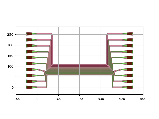
luceda-academy/training/topical_training/routing_chip_edge/example_bundle.py
Example 1: Splitter Tree North
This example illustrates the application of a routing heuristic on a splitter tree oriented in the horizontal direction with grating couplers placed north of the chip.
Both bundles and chained connectors are used.
The biggest difference with the simpler examples shown above is how the waypoints are specified.
Here, the position of the waypoints is calculated from the position and size of instances that have already been placed in the circuit.
This is done using the layout views of specific instance variables, as provided to i3.Circuit.
Note
The following example uses the splitter tree designed in the P-Team Library built on top of SiFab (pteam_library_si_fab).
For the import statement to work, add the folder libraries/pteam_libraries_si_fab/ipkiss to the PYTHONPATH (right-click > Mark Directory as > Sources Root).
import si_fab.all as pdk
from ipkiss3 import all as i3
from pteam_library_si_fab.all import SplitterTree
import numpy as np
import os


class RouteSplitterTreeNorth(i3.Circuit):
    """Routed Splitter tree with grating couplers placed north."""

    dut = i3.ChildCellProperty(doc="splitter used")
    grating = i3.ChildCellProperty(doc="Splitter")
    grating_sep = i3.PositiveNumberProperty(default=50.0, doc="Separation between the gratings")
    bend_radius = i3.PositiveNumberProperty(default=20.0, doc="Bend Radius")
    wav_sep = i3.PositiveNumberProperty(default=8.0, doc="Separation between waveguides")

    def _default_grating(self):
        return pdk.FC_TE_1550()

    def _default_bend_radius(self):
        return 20.0

    def _default_dut(self):
        return SplitterTree(name=self.name + "_DUT", levels=6)

    def _default_insts(self):
        instances = dict()
        instances["DUT"] = self.dut
        for cnt in range(2**self.dut.levels):
            instances[f"gr_out_{cnt}"] = self.grating
        instances["gr_in"] = self.grating

        return instances

    def _default_specs(self):
        si_dut = self.dut.get_default_view(i3.LayoutView).size_info()
        nw = si_dut.north_west
        gr_y = nw[1] + (1 + np.ceil(si_dut.width / self.grating_sep)) * self.wav_sep + 5 * self.bend_radius
        specs = [
            i3.Place("DUT", (0, 0)),
            i3.Place("gr_in:out", (nw[0] - 1 * self.grating_sep, gr_y), angle=-90),
            i3.ConnectManhattan("gr_in:out", "DUT:in", bend_radius=self.bend_radius, min_straight=0.0),
        ]

        wp_x = si_dut.east + self.bend_radius
        wp_y = si_dut.north + 2 * self.bend_radius
        n_gratings = 2**self.dut.levels
        for cnt in range(n_gratings):
            pos_grating_port = (nw[0] + cnt * self.grating_sep, gr_y)
            specs.append(i3.Place(f"gr_out_{cnt}:out", pos_grating_port, angle=-90))

            tt_grating_port = self.grating.get_default_view(i3.LayoutView).ports["out"].trace_template

            wp_x += self.wav_sep
            if pos_grating_port[0] > wp_x:
                wp_y -= self.wav_sep
            else:
                wp_y += self.wav_sep

            if np.abs(pos_grating_port[0] - wp_x) < 2 * self.bend_radius:
                intermediate_port = i3.OpticalPort(
                    name=f"intermediate_port_{cnt}",
                    position=(wp_x, wp_y),
                    angle=90,
                    trace_template=tt_grating_port,
                )

                specs.extend(
                    [
                        i3.ConnectBend(f"gr_out_{cnt}:out", intermediate_port, bend_radius=self.bend_radius),
                        i3.ConnectManhattan(
                            intermediate_port.flip_copy(),
                            f"DUT:out{n_gratings - cnt}",
                            bend_radius=self.bend_radius,
                            min_straight=0.0,
                            start_straight=0.0,
                        ),
                    ]
                )

            else:
                specs.append(
                    i3.ConnectManhattan(
                        f"gr_out_{cnt}:out",
                        f"DUT:out{n_gratings - cnt}",
                        control_points=[i3.H(wp_y), i3.V(wp_x)],
                        bend_radius=self.bend_radius,
                        min_straight=0.0,
                        start_straight=0.0,
                    )
                )

        return specs


if __name__ == "__main__":
    project_folder = "./splitter_tree_north"  # Name of the project
    if not os.path.exists(project_folder):
        os.mkdir(project_folder)
    for levels in range(1, 7):
        print(f"Number levels:{levels}")
        dut = SplitterTree(name=f"SP{levels}", levels=levels)
        cell = RouteSplitterTreeNorth(name=f"Routed_tree{levels}", dut=dut)
        cell_lv = cell.Layout()
        fig = cell_lv.visualize(show=False)
        fig.savefig(
            os.path.join(project_folder, f"routed_tree_{levels}.png"),
            transparent=True,
            bbox_inches="tight",
        )
        cell_lv.write_gdsii(os.path.join(project_folder, f"splitter_tree_routed_north_{levels}.gds"))
        print("done")
Let’s analyze the code in a bit more detail.
The overall cell inherits from i3.Circuit and defines cell “instances” that constitute our circuit and the placement and routing specs.
This is done by implementing the methods _default_insts and _default_specs.
Step 1: Definition of the instances
    def _default_insts(self):
        instances = dict()
        instances["DUT"] = self.dut
        for cnt in range(2**self.dut.levels):
            instances[f"gr_out_{cnt}"] = self.grating
        instances["gr_in"] = self.grating
The first instance we place is the DUT, or device-under-test, which is passed on as a i3.ChildCellProperty.
The reason we do that is to allow the DUT to be defined externally to the class and passed on as a property.
Next we have a for loop for all the output grating couplers as well as the input grating coupler.
Step 2: Definition of the placement and routing specifications
    def _default_specs(self):
        si_dut = self.dut.get_default_view(i3.LayoutView).size_info()
        nw = si_dut.north_west
        gr_y = nw[1] + (1 + np.ceil(si_dut.width / self.grating_sep)) * self.wav_sep + 5 * self.bend_radius
        specs = [
            i3.Place("DUT", (0, 0)),
            i3.Place("gr_in:out", (nw[0] - 1 * self.grating_sep, gr_y), angle=-90),
            i3.ConnectManhattan("gr_in:out", "DUT:in", bend_radius=self.bend_radius, min_straight=0.0),
        ]

        wp_x = si_dut.east + self.bend_radius
        wp_y = si_dut.north + 2 * self.bend_radius
        n_gratings = 2**self.dut.levels
        for cnt in range(n_gratings):
            pos_grating_port = (nw[0] + cnt * self.grating_sep, gr_y)
            specs.append(i3.Place(f"gr_out_{cnt}:out", pos_grating_port, angle=-90))

            tt_grating_port = self.grating.get_default_view(i3.LayoutView).ports["out"].trace_template

            wp_x += self.wav_sep
            if pos_grating_port[0] > wp_x:
                wp_y -= self.wav_sep
            else:
                wp_y += self.wav_sep

            if np.abs(pos_grating_port[0] - wp_x) < 2 * self.bend_radius:
                intermediate_port = i3.OpticalPort(
                    name=f"intermediate_port_{cnt}",
                    position=(wp_x, wp_y),
                    angle=90,
                    trace_template=tt_grating_port,
                )

                specs.extend(
                    [
                        i3.ConnectBend(f"gr_out_{cnt}:out", intermediate_port, bend_radius=self.bend_radius),
                        i3.ConnectManhattan(
                            intermediate_port.flip_copy(),
                            f"DUT:out{n_gratings - cnt}",
                            bend_radius=self.bend_radius,
                            min_straight=0.0,
                            start_straight=0.0,
                        ),
                    ]
                )

            else:
                specs.append(
                    i3.ConnectManhattan(
                        f"gr_out_{cnt}:out",
                        f"DUT:out{n_gratings - cnt}",
                        control_points=[i3.H(wp_y), i3.V(wp_x)],
                        bend_radius=self.bend_radius,
                        min_straight=0.0,
                        start_straight=0.0,
                    )
                )

        return specs
The second step is the definition of the specifications.
The first thing we do is to calculate the size_info of the DUT.
This object contains information on the size of the DUT and allows for the relative positioning of the grating couplers.
The y-position of the grating couplers gr_y is calculated using the y-value of the north-west corner of the
DUT plus some room for the waveguides.
The formula
gr_y = nw[1] + (1 + np.ceil(si_dut.width / self.grating_sep)) * self.wav_sep + 5 * self.bend_radius
was obtained through thinking and some iterations.
The definition of the routing specifications is based on the routing heuristic using conditional waypoints and connectors.
In the following picture we annotated the layout of RouteSplitterTreeNorth with the points where the connectors initially bend.
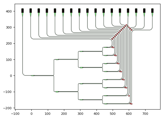
The red dots are the bending points that are specified in the manhattan route by where the horizontal and the vertical parts of the route have to pass through i3.H(wp_y) and i3.V(wp_x) (see i3.H and i3.V).
This ensures that the route will bend at (wp_x, wp_y).
The brown dot is the waypoint used in the case of an S-bend route (wp_x, wp_y).
The value of wp_x and wp_y is increased or decreased depending on the relative position of the current waypoint and the grating coupler.
            wp_x += self.wav_sep
            if pos_grating_port[0] > wp_x:
                wp_y -= self.wav_sep
            else:
                wp_y += self.wav_sep
Similarly, the connector itself depends on the relative position as well. An S-bend is needed in case there is no space for a lateral bend when the grating coupler sits more or less on top of (wp_x, wp_y).
            if np.abs(pos_grating_port[0] - wp_x) < 2 * self.bend_radius:
                intermediate_port = i3.OpticalPort(
                    name=f"intermediate_port_{cnt}",
                    position=(wp_x, wp_y),
                    angle=90,
                    trace_template=tt_grating_port,
                )

                specs.extend(
                    [
                        i3.ConnectBend(f"gr_out_{cnt}:out", intermediate_port, bend_radius=self.bend_radius),
                        i3.ConnectManhattan(
                            intermediate_port.flip_copy(),
                            f"DUT:out{n_gratings - cnt}",
                            bend_radius=self.bend_radius,
                            min_straight=0.0,
                            start_straight=0.0,
                        ),
                    ]
                )

            else:
                specs.append(
                    i3.ConnectManhattan(
                        f"gr_out_{cnt}:out",
                        f"DUT:out{n_gratings - cnt}",
                        control_points=[i3.H(wp_y), i3.V(wp_x)],
                        bend_radius=self.bend_radius,
                        min_straight=0.0,
                        start_straight=0.0,
                    )
                )
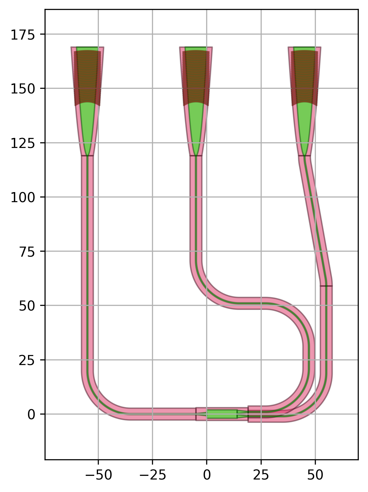
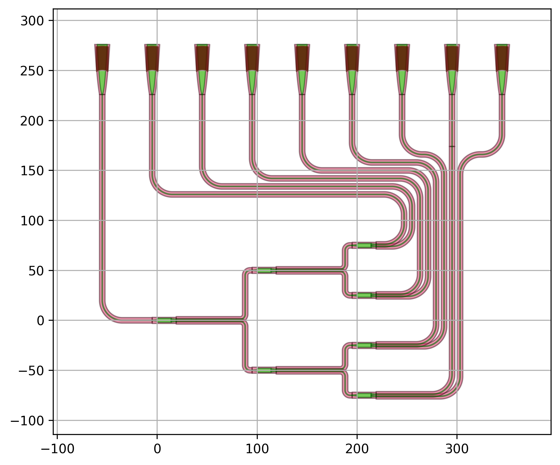
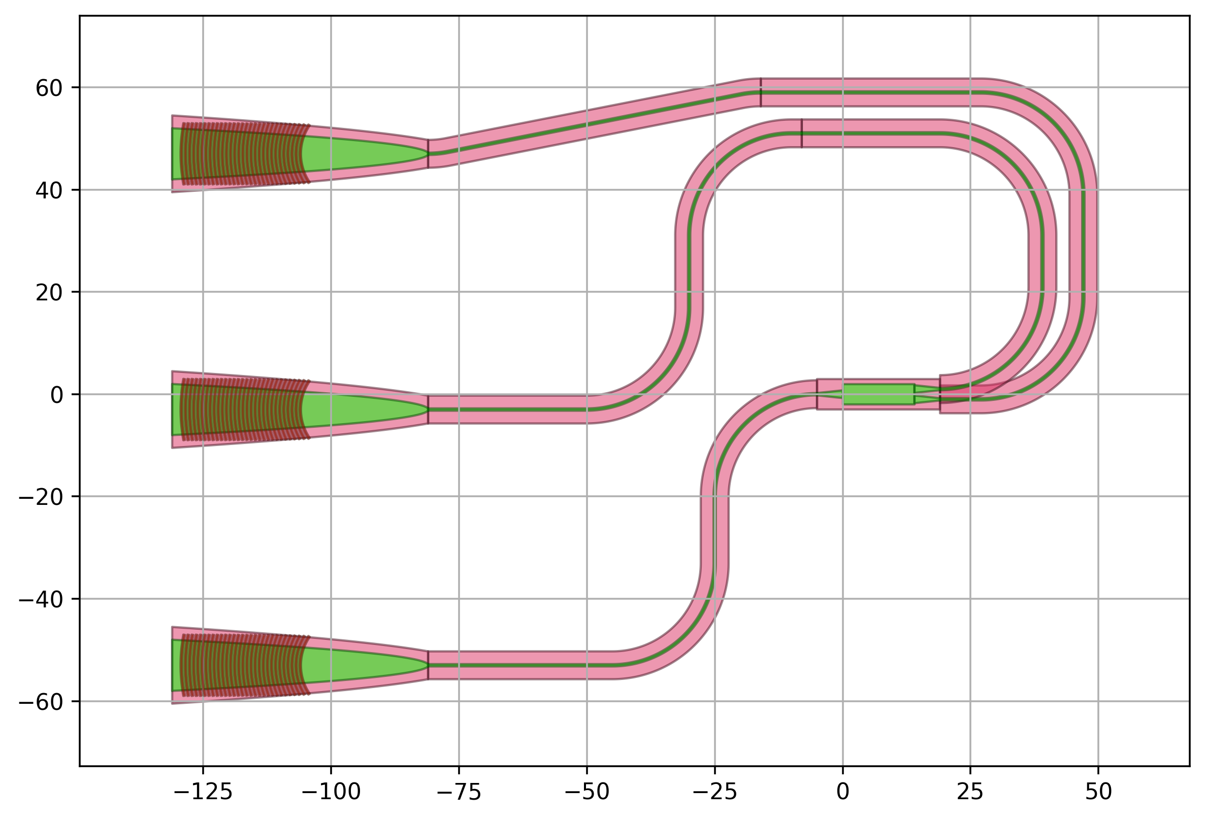
In what follows, we plot the layout of a routed splitter tree with varying number of levels.
The instances (including the connector instances) are automatically placed in the Layout view based on the specs using i3.place_and_route.
1 level
3 levels
6 levels
Example 2: Splitter Tree West
This example is similar to the first one, but we route the splitter tree to grating couplers placed west of the circuit.
import si_fab.all as pdk
from ipkiss3 import all as i3
from pteam_library_si_fab.all import SplitterTree
import numpy as np
import os


class RouteSplitterTreeWest(i3.Circuit):
    """Routed Splitter tree with grating couplers placed west."""

    dut = i3.ChildCellProperty(doc="splitter used")
    grating = i3.ChildCellProperty(doc="Splitter")
    grating_sep = i3.PositiveNumberProperty(default=50.0, doc="Separation between the gratings")
    bend_radius = i3.PositiveNumberProperty(default=20.0, doc="Bend Radius")
    wav_sep = i3.PositiveNumberProperty(default=8.0, doc="Separation between waveguides")

    def _default_grating(self):
        return pdk.FC_TE_1550()

    def _default_bend_radius(self):
        return 20.0

    def _default_dut(self):
        return SplitterTree(name=self.name + "_DUT", levels=6)

    def _default_insts(self):
        instances = dict()
        instances["DUT"] = self.dut
        for inst in range(2**self.dut.levels):
            instances[f"gr_out_{inst}"] = self.grating
        instances["gr_in"] = self.grating
        return instances

    def _default_specs(self):
        dut_lo = self.dut.get_default_view(i3.LayoutView)
        si_dut = dut_lo.size_info()
        # dut_port
        sw = si_dut.south_west
        nw = si_dut.north_west
        n_gratings = 2**self.dut.levels
        gr_x = sw[0] - n_gratings * self.wav_sep - 3 * self.bend_radius
        specs = [
            i3.Place("DUT", (0, 0)),
            i3.Place("gr_in:out", (gr_x, sw[1] - self.grating_sep)),
            i3.ConnectManhattan("gr_in:out", "DUT:in", bend_radius=self.bend_radius, min_straight=0),
        ]

        wp_x = nw[0] - sw[0]
        for cnt in range(n_gratings):
            pos_grating_port = (gr_x, sw[1] + cnt * self.grating_sep)
            specs.append(i3.Place(f"gr_out_{cnt}:out", pos_grating_port))
            tt_grating_port = self.grating.get_default_view(i3.LayoutView).ports["out"].trace_template

            wp_y = nw[1] + (cnt + 1) * self.wav_sep + 2 * self.bend_radius
            if pos_grating_port[1] > wp_y:
                wp_x += self.wav_sep
            else:
                wp_x -= self.wav_sep

            intermediate_port = i3.OpticalPort(
                name=f"intermediate_port_{cnt}",
                position=(wp_x, wp_y),
                angle=180,
                trace_template=tt_grating_port,
            )
            if np.abs(pos_grating_port[1] - wp_y) < 2 * self.bend_radius:
                specs.append(
                    i3.ConnectBend(
                        f"gr_out_{cnt}:out",
                        intermediate_port,
                        f"connect_gc_{cnt}",
                        bend_radius=self.bend_radius,
                    )
                )
            else:
                specs.append(
                    i3.ConnectManhattan(
                        f"gr_out_{cnt}:out",
                        intermediate_port,
                        bend_radius=self.bend_radius,
                    )
                )

            specs.append(
                i3.ConnectManhattan(
                    f"DUT:out{n_gratings - cnt}",
                    intermediate_port.flip_copy(),
                    control_points=[
                        i3.V(self.bend_radius + cnt * self.wav_sep, relative_to=f"DUT:out{n_gratings - cnt}")
                    ],
                    bend_radius=self.bend_radius,
                    min_straight=0.0,
                )
            )

        return specs


if __name__ == "__main__":
    project_folder = "./splitter_tree_west"  # Name of the project
    if not os.path.exists(project_folder):
        os.mkdir(project_folder)

    for levels in range(1, 7):
        print(f"Number levels:{levels}")
        dut = SplitterTree(name=f"SP{levels}", levels=levels)
        cell = RouteSplitterTreeWest(name=f"Routed_tree{levels}", dut=dut)
        cell_lv = cell.Layout()
        fig = cell_lv.visualize(show=False)
        fig.savefig(
            os.path.join(project_folder, f"routed_tree_{levels}.png"),
            transparent=True,
            bbox_inches="tight",
        )
        cell_lv.write_gdsii(os.path.join(project_folder, f"splitter_tree_routed_west_{levels}.gds"))
        print("done")
The routing is parametric and can be applied to any number of levels.
1 level
3 levels
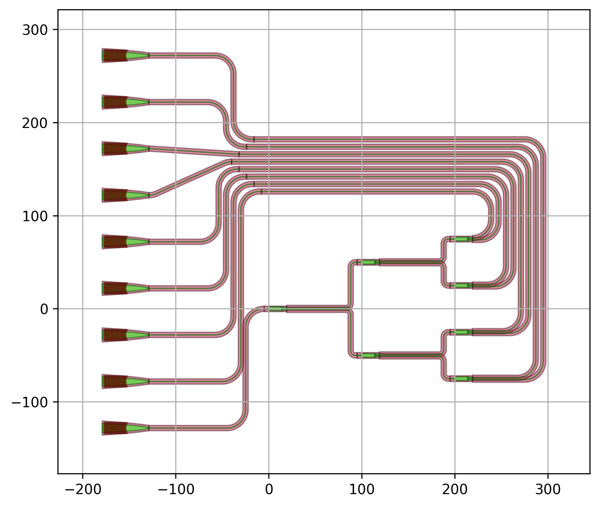
6 levels
