Trace templates
Every waveguide has a trace template which holds information about its cross-section and the simulation model linked to the cross-section. Every port used in a circuit also carries a trace template. When we are discussing waveguides, we can also use the term waveguide template for their trace template.
Trace templates are needed to create every connection inside a circuit, but do not often have to be defined explicitly. If you use predefined components from a PDK to design a circuit, these ports already have a trace template, so you don’t need to assign one manually. In a connector, the trace templates of the specified start port and end port are used to generate a connection. You can specify a trace template as a parameter of a connector, but this is not required and only implemented in specific cases.
In this section you will first learn what is defined inside a trace template. Next, you will see how a connector generates connections between two ports with different trace templates. After that, you will learn how to specify a trace template inside your connector. Finally, you will discover how to customize your own trace template.
What’s a trace template?
A trace template decouples the general properties of a waveguide from its cross-section. It is a parametric cell with a Layout view and a CircuitModel view.
Layout view: In the Layout view of a trace template, a list of windows is defined. Each window is drawn on a specific layer in the technology of the PDK you’re using and has a specific width and position. From this list, a cross-section can be virtually fabricated. What this cross-section looks like depends on the PDK being used.
CircuitModel view: In the CircuitModel view of a trace template, some aspects that could be extracted from the cross-section of a waveguide are defined, such as the simulation model (e.g. the effective index and group index of the waveguide).
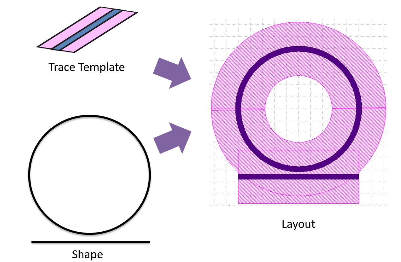
Trace templates are used to create waveguides and are assigned to all of your used ports in your circuit.
In the picture below, a ring resonator is created by combining waveguides in a circuit. All of these waveguides are created by drawing the same trace template over a specified shape. This means that all of the exposed ports of the ring resonator share the same trace template, and therefore all have the same cross-section.
Connection between ports with different trace templates
In the previous section, the output ports of grating couplers were connected using connectors. These ports all had the same trace template. It is also possible to connect two ports with a different trace template by making use of one connector.
Let’s start by instantiating four different trace templates from the si_fab PDK and set the width of the core and cladding layers:
from si_fab import all as pdk
from ipkiss3 import all as i3

# Define trace templates for the ports
tt1 = pdk.SiWireWaveguideTemplate()
tt1.Layout(core_width=0.4, cladding_width=5.0)

tt2 = pdk.SiWireWaveguideTemplate()
tt2.Layout(core_width=1.5, cladding_width=5.0)

tt3 = pdk.SiRibWaveguideTemplate()
tt3.Layout(core_width=0.4, cladding_width=5.0)

tt4 = pdk.SiRibWaveguideTemplate()
tt4.Layout(core_width=1.5, cladding_width=5.0)
pdk.SiWireWaveguideTemplate represents the trace template of a wire waveguide with a specific core width and cladding width. pdk.SiRibWaveguideTemplate represents the trace template of a rib waveguide with a specific core width and a shallow etched layer width (also set by the parameter cladding_width). So both trace templates consist of two windows representing different layers.
Let’s now assign these trace templates to some optical ports. These ports could be the input or output port of any optical component in a circuit.
# Define some ports
port1 = i3.OpticalPort(position=(0.0, 40.0), name="port1", angle=0.0, trace_template=tt1)
port2 = i3.OpticalPort(position=(0.0, 20.0), name="port2", angle=0.0, trace_template=tt3)
port3 = i3.OpticalPort(position=(0.0, 0.0), name="port3", angle=0.0, trace_template=tt2)
port4 = i3.OpticalPort(position=(60.0, 40.0), name="port4", angle=180.0, trace_template=tt2)
port5 = i3.OpticalPort(position=(60.0, 20.0), name="port5", angle=180.0, trace_template=tt4)
port6 = i3.OpticalPort(position=(60.0, 0.0), name="port6", angle=180.0, trace_template=tt4)
Next, we create three connectors between these ports using i3.ConnectManhattan:
The first connector links two wire waveguide trace templates with different core widths.
The second connector also links waveguides with different core widths but uses rib waveguide templates.
The third connector links a wire waveguide template to a rib waveguide template.
# Create connections
specs = [
    i3.ConnectManhattan(port1, port4, "wire_to_wire"),
    i3.ConnectManhattan(port2, port5, "rib_to_rib", end_taper_length=20),
    i3.ConnectManhattan(port3, port6, "wire_to_rib", end_taper_length=30),
]

connectors = i3.Circuit(specs=specs)
connectors_lo = connectors.Layout()
connectors_lo.visualize()
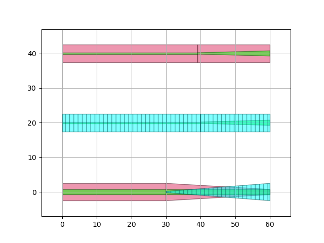
You can see that, in each case, because the trace templates of the two ports are different, the generated connection is composed of two separate blocks: a waveguide and a taper.
The first block (waveguide) uses the trace template of the start_port of the connector, while the second block (taper) tapers from the trace template of the start_port to the trace template of the end_port.
The taper length of the second block can be adjusted using the end_taper_length parameter.
In the third connection (wire to rib transition), you can see that the wire and rib trace templates have different sets of layers, with only the core layer being the same. The cladding layer of the wire trace template tapers out completely until it no longer exists. Meanwhile, the shallow etched layer of the rib template is created at the start of the taper and gradually tapers to its defined width at the end.
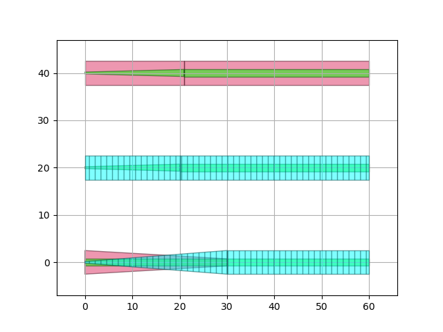
If we now switch the start_port and end_port of these connectors, you will see that the tapering happens at the opposite port.
# Create connections with switched ports
specs = [
    i3.ConnectManhattan(port4, port1, "wire_to_wire"),
    i3.ConnectManhattan(port5, port2, "rib_to_rib", end_taper_length=20),
    i3.ConnectManhattan(port6, port3, "wire_to_rib", end_taper_length=30),
]
connectors_switched = i3.Circuit(specs=specs)
connectors_switched_lo = connectors_switched.Layout()
connectors_switched_lo.visualize()
Connection with trace template as parameter
It is also possible to specify a trace template as a parameter of a connector.
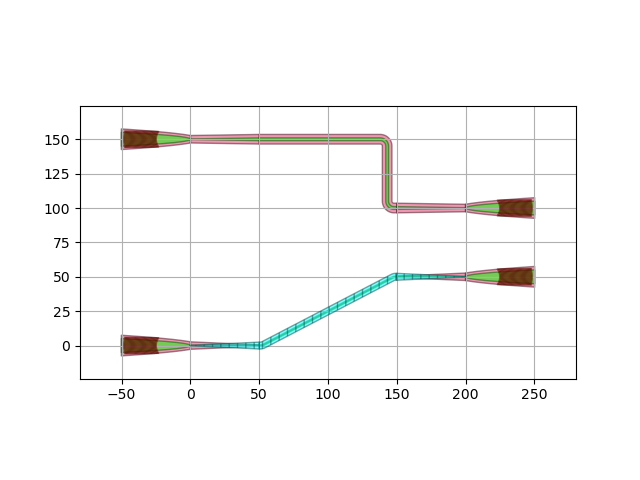
In this case the connector will create three separate blocks: two tapers and one waveguide.
The connection will taper from the trace template of the starting port to the inserted trace template and finally taper out to the trace template of the end port.
The lengths of the taper sections can be defined in the connectors’ parameters.
In the following code, a trace template is specified in a i3.ConnectManhattan connector and a i3.ConnectBend connector each connecting two grating couplers.
import si_fab.all as pdk

import ipkiss3.all as i3

# Define and instantiate grating couplers
gc = pdk.FC_TE_1550()

specs = [i3.Inst(["gc_in1", "gc_in2", "gc_out1", "gc_out2"], gc)]

# Define trace templates
tt1 = pdk.SiWireWaveguideTemplate()
tt1.Layout(core_width=2)

tt2 = pdk.SiRibWaveguideTemplate()
tt2.Layout(core_width=1, cladding_width=5.0)

# Place and route grating couplers
specs += [
    i3.Place("gc_in1:out", (0, 150)),
    i3.Place("gc_in2:out", (0, 0)),
    i3.Place("gc_out1:out", (200, 100), angle=180),
    i3.Place("gc_out2:out", (200, 50), angle=180),
    i3.ConnectManhattan(
        "gc_in1:out",
        "gc_out1:out",
        trace_template=tt1,
        start_taper_length=50,
        end_taper_length=50,
    ),
    i3.ConnectBend(
        "gc_in2:out",
        "gc_out2:out",
        trace_template=tt2,
        start_taper_length=50,
        end_taper_length=50,
    ),
]

# Create and visualize circuit
circuit = i3.Circuit(specs=specs)
circuit_lo = circuit.Layout()
circuit_lo.visualize()
Customize trace template
Most trace templates can be created starting from the trace templates available in the si_fab PDK or other design kits.
However, if a specific trace template for your design is not available in the library, you may need to create your own.
This can be achieved by creating a class that inherits from i3.WindowWaveguideTemplate.
In this example, a trace template for a slot waveguide is created. A slot waveguide is a specific type of waveguide where light is guided through a slot section with low refractive index. These waveguides are widely used in various photonic applications.
As mentioned before, the layout of a trace template consists of a list of windows. Let’s have a look at the code for the Layout view of our customized trace template for a simple slot waveguide.
import si_fab.all as pdk
import ipkiss3.all as i3


class MySlotWgTemplate(i3.WindowWaveguideTemplate):
    class Layout(i3.WindowWaveguideTemplate.Layout):
        slot_width = i3.PositiveNumberProperty(doc="width of the slot section")
        slab_width = i3.PositiveNumberProperty(doc="width of the slab sections")
        cladding_width = i3.PositiveNumberProperty(doc="width of the cladding")

        def _default_slot_width(self):
            return 0.2

        def _default_slab_width(self):
            return 1.0

        def _default_cladding_width(self):
            return 4.0

        def _default_windows(self):
            return [
                i3.PathTraceWindow(
                    layer=pdk.TECH.PPLAYER.SI,
                    start_offset=-0.5 * self.slot_width - self.slab_width,
                    end_offset=-0.5 * self.slot_width,
                ),
                i3.PathTraceWindow(
                    layer=pdk.TECH.PPLAYER.SI,
                    start_offset=0.5 * self.slot_width,
                    end_offset=0.5 * self.slot_width + self.slab_width,
                ),
                i3.PathTraceWindow(
                    layer=pdk.TECH.PPLAYER.SI_CLADDING,
                    start_offset=-0.5 * self.cladding_width,
                    end_offset=0.5 * self.cladding_width,
                ),
            ]
First, some parameters are defined to correctly position the windows.
The width of the slot section is defined by slot_width, while the width of both cores is specified by slab_width.
Additionally, the width of the cladding is defined by cladding_width.
With these parameters in place, we can now create the windows.
The windows are created using i3.PathTraceWindow and positioned by introducing a start_offset and an end_offset relative to the center.
In this example, one cladding layer window and two core layer windows are created in _default_windows.
Below, you can see a visualization of the cross-section and the layout of a waveguide created with this trace template. The waveguide is a straight section with a length of 10 µm, and the cross-section path is perpendicular to the propagation direction.
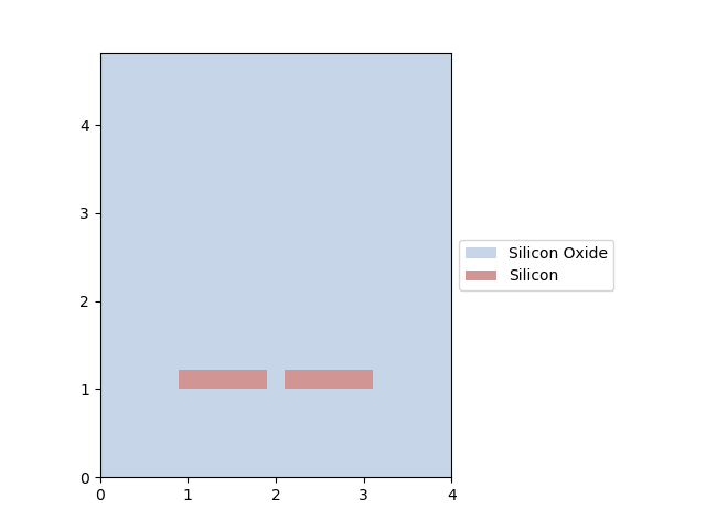
Cross-section of an example of a slot waveguide
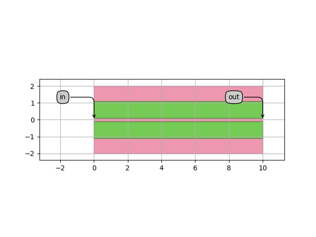
Layout of an example of a slot waveguide
In the next section, we will explore how to create waveguides using trace templates.