ManhattanFanout
- class ipkiss3.all.ManhattanFanout
Create L-bend-like routes that fanout all the start ports to evenly spaced outputs. To be used with a bundle connector.
- Parameters:
- end_position: ( Coord2 ), optional, *None allowed*
The coordinate where the reference route ends. If None, the fanout is made as compact as possible.This parameter is used as an ‘anchor’ to start the Manhattan bundle route
- reference: optional, *None allowed*
Port (instance:port identifier or an actual i3.Port) to align the fanout with. If None, the center of the inputs is used as reference.
- output_direction: optional
Direction of the output waveguides. Should be EAST, WEST, NORTH or SOUTH.Defaults to DIRECTION.EAST.
See also
Examples
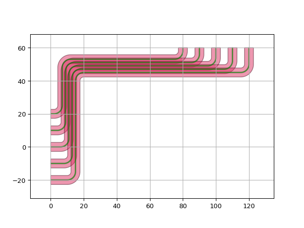
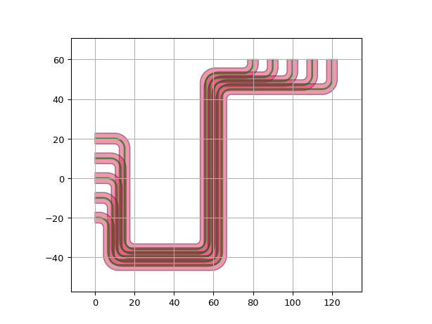
Use output_direction to control the direction of the waveguides:
import si_fab.all as pdk  # noqa
import ipkiss3.all as i3

start_ports = [
    i3.OpticalPort(name=f"start_port_{i}", position=(0.0, -20.0 + 10 * i), angle=0) for i in range(5)
]
end_ports = [i3.OpticalPort(name=f"end_port_{i}", position=(120 - 10 * i, 60), angle=-90) for i in range(5)]

circuit = i3.Circuit(
    specs=[
        i3.ConnectManhattanBundle(
            connections=list(zip(start_ports, end_ports)),
            start_fanout=i3.ManhattanFanout(
                # Route start_fanout to NORTH
                output_direction=i3.NORTH,
            ),
            end_fanout=i3.ManhattanFanout(
                # Route end_fanout to WEST
                output_direction=i3.WEST,
            ),
        )
    ]
)

lv = circuit.Layout()
lv.visualize()

circuit = i3.Circuit(
    specs=[
        i3.ConnectManhattanBundle(
            connections=list(zip(start_ports, end_ports)),
            start_fanout=i3.ManhattanFanout(
                # Route start_fanout to SOUTH
                output_direction=i3.SOUTH,
            ),
            end_fanout=i3.ManhattanFanout(
                # Route end_fanout to WEST
                output_direction=i3.WEST,
            ),
        )
    ]
)

lv = circuit.Layout()
lv.visualize()
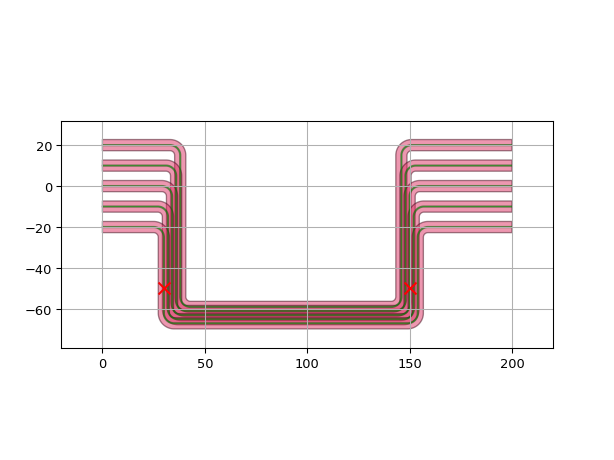
Use actual i3.Port as reference and end_position to control the alignment of the fanout:
import si_fab.all as pdk  # noqa: F401
import matplotlib.pyplot as plt
import ipkiss3.all as i3

start_ports = [
    i3.OpticalPort(name=f"start_port_{i}", position=(0.0, -20.0 + 10 * i), angle=0) for i in range(5)
]
end_ports = [
    i3.OpticalPort(name=f"end_port_{i}", position=(200.0, -20.0 + 10 * i), angle=180) for i in range(5)
]

circuit = i3.Circuit(
    specs=[
        i3.ConnectManhattanBundle(
            connections=list(zip(start_ports, end_ports)),
            start_fanout=i3.ManhattanFanout(
                # Route start_fanout to SOUTH
                output_direction=i3.SOUTH,
                # Route the first start port to (30, -50)
                reference=start_ports[0],
                end_position=(30, -50),
            ),
            end_fanout=i3.ManhattanFanout(
                # Route end_fanout to SOUTH
                output_direction=i3.SOUTH,
                # Route the center of the inputs to (150, -50)
                end_position=(150, -50),
            ),
        )
    ]
)

lv = circuit.Layout()
lv.visualize(show=False)
plt.scatter(
    30, -50, marker="x", color="r", s=80, zorder=50
)  # end_position for the reference of the start_fanout
plt.scatter(
    150, -50, marker="x", color="r", s=80, zorder=50
)  # end_position for the reference of the end_fanout
plt.show()
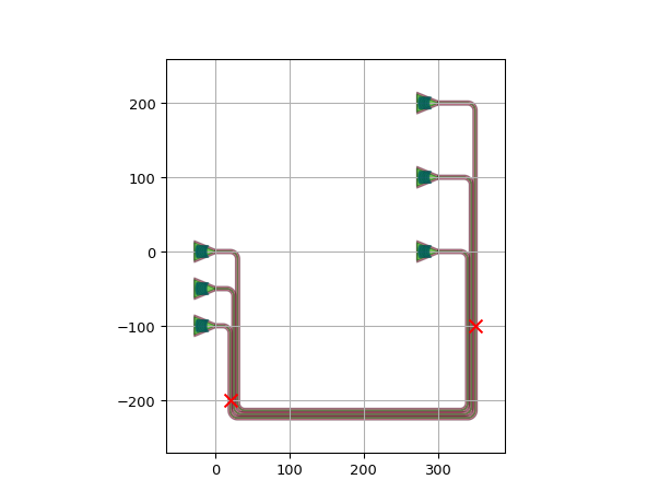
Use ‘instance:port’ as reference and end_position to control the alignment of the fanout:
import si_fab.all as pdk  # noqa: F401
from picazzo3.fibcoup.curved import FiberCouplerCurvedGrating
import ipkiss3.all as i3
import matplotlib.pyplot as plt

fc = FiberCouplerCurvedGrating()

circuit = i3.Circuit(
    insts={
        "fc1": fc,
        "fc2": fc,
        "fc3": fc,
        "fc4": fc,
        "fc5": fc,
        "fc6": fc,
    },
    specs=[
        i3.Place("fc1:out", (0.0, 0.0), angle=0.0),
        i3.Place("fc2:out", (0.0, -50.0), angle=0.0),
        i3.Place("fc3:out", (0.0, -100.0), angle=0.0),
        i3.Place("fc4:out", (300.0, 0.0), angle=0.0),
        i3.Place("fc5:out", (300.0, 100.0), angle=0.0),
        i3.Place("fc6:out", (300.0, 200.0), angle=0.0),
        i3.ConnectManhattanBundle(
            connections=[
                ("fc1:out", "fc4:out"),
                ("fc2:out", "fc5:out"),
                ("fc3:out", "fc6:out"),
            ],
            start_fanout=i3.ManhattanFanout(
                # Route start_fanout to SOUTH
                output_direction=i3.SOUTH,
                # Route "fc3:out" to (20, -200)
                reference="fc3:out",
                end_position=(20, -200),
            ),
            end_fanout=i3.ManhattanFanout(
                # Route end_fanout to SOUTH
                output_direction=i3.SOUTH,
                # Route "fc6:out" to (350, -100)
                reference="fc6:out",
                end_position=(350, -100),
            ),
            pitch=5,
            bend_radius=10,
        ),
    ],
)

circuit_lo = circuit.Layout()
circuit_lo.visualize(show=False)
plt.scatter(
    20, -200, marker="x", color="r", s=80, zorder=50
)  # end_position for the reference of the start_fanout
plt.scatter(
    350, -100, marker="x", color="r", s=80, zorder=50
)  # end_position for the reference of the end_fanout
plt.show()
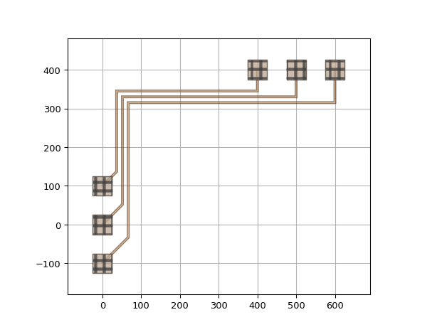
Use ManhattanFanout in electrical bundle:
import si_fab.all as pdk  # noqa: F401
import ipkiss3.all as i3

bp = pdk.BondPad()
M1_wire_tpl = pdk.M1WireTemplate().Layout(width=5)

circuit = i3.Circuit(
    insts={
        "pad1": bp,
        "pad2": bp,
        "pad3": bp,
        "pad4": bp,
        "pad5": bp,
        "pad6": bp,
    },
    specs=[
        i3.Place("pad1:m1", (0.0, -100.0)),
        i3.Place("pad2:m1", (0.0, 0.0)),
        i3.Place("pad3:m1", (0.0, 100.0)),
        i3.Place("pad4:m1", (400.0, 400)),
        i3.Place("pad5:m1", (500.0, 400)),
        i3.Place("pad6:m1", (600.0, 400)),
        i3.ConnectElectricalBundle(
            connections=[
                ("pad1:m1", "pad6:m1"),
                ("pad2:m1", "pad5:m1"),
                ("pad3:m1", "pad4:m1"),
            ],
            start_angle=45,
            start_straight=50,
            start_fanout=i3.ManhattanFanout(output_direction=i3.NORTH),
            end_angle=-90.0,
            end_straight=50,
            end_fanout=i3.ManhattanFanout(output_direction=i3.WEST),
            trace_template=M1_wire_tpl,
            pitch=15,
            min_gap=5,
        ),
    ],
)

circuit_lo = circuit.Layout()
circuit_lo.visualize()
