ConnectManhattanTapered
- class ipkiss3.all.ConnectManhattanTapered
A connector that uses
i3.RouteManhattanto connect two ports and returns a waveguide with a different trace template in the straight sections.- Parameters:
- straight_section_positions: ( list<fraction> ), optional, *None allowed*
A list of relative positions for the straight_template sections of each path segment. Length of list must be identical to number of segments.Each position is a number between 0 (closest to first waypoint) and 1 (closest to last waypoint).0.5 will place the expanded section in the middle of the segment.If unspecified, the default from i3.TaperedWaveguide is used.
- straight_section_lengths: ( list<number >= 0> ), optional, *None allowed*
A list of lengths for the straight_template sections of each path segment.Length of list must be identical to number of segmentsIf unspecified, the default from i3.TaperedWaveguide is used.
- min_straight_section_length: float and int, float, integer, floating and number >= 0, optional
minimum_length of the straight sections.
- taper_lengths: ( list<number >= 0> ), optional, *None allowed*
Lengths of the tapers for each section. Length of list must be identical to number of segments.If unspecified, the default from i3.TaperedWaveguide is used.
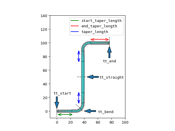
- taper_length: ( float and int, float, integer, floating and number >= 0 ), optional, *None allowed*
length of the taper between the regular waveguide and the expanded waveguide.Ignored if taper_lengths is set. If unspecified, the default from i3.TaperedWaveguide is used.
- straight_trace_template: ( PCell and _TraceTemplate ), optional, *None allowed*
template for the straight sections. If unspecified, the trace template of the start port is used and no tapering is applied.
- match_path_length: ( MatchLength ), optional, *None allowed*
Optional settings for length matching. Must be an instance of
i3.MatchLength. Requires one H/V control point with flexible set to True.- cover_layers: List with type restriction, allowed types: <class ‘ipkiss.primitives.layer.Layer’>, optional
Layers that can be used to generate additional coverage of the trace (e.g. manhattan corners). The ‘cover_bends’ property has to be set to True for this to take effect.
- cover_bends: optional
Adds rectangular blocks in the bends to avoid as much as possible non-manhattan angles. Needs to be configured together with the ‘cover_layers’ property.
- fixed_bend90: ( PCell ), optional, *None allowed*
An optional override for the 90 degree bends used in the routing. The bend should have exactly two optical ports and the angle of the bend should be equal to 90 degrees. The trace template of the bend should match trace_template. Bends are assumed to be bi-directional in the routing. If the route requires non 90 degree angles, they will generated using bend_radius, angle_step and rounding_algorithm. Likewise when there isn’t enough space to place the fixed bend, it will be replaced by an autogenerated one.
- min_spacing: float and int, float, integer, floating and number >= 0, optional
minimal spacing between parallel sections of the route
- end_straight: float and int, float, integer, floating and number >= 0, optional
The length of the straight end section of the route
- start_straight: float and int, float, integer, floating and number >= 0, optional
The length of the straight start section of the route
- min_straight: float and int, float, integer, floating and number >= 0, optional
The minimum length of any straight sections in the route
- angle_step: float and number > 0, optional
angle step for rounding
- rounding_algorithm: optional
Rounding algorithm (ShapeRound, ShapeRoundAdiabaticSpline, …). Takes a shape as input and returns a new (rounded) shape.
- bend_radius: float and number > 0, optional
bend radius for the auto-generated bends
- control_points: list, optional
Control the routing by passing either a list of points
i3.CPthrough which the route has to pass,or a list ofi3.H/i3.Vinstances.- end_taper_length: ( float and int, float, integer, floating and number >= 0 ), optional, *None allowed*
Length of the taper for the transition to be generated at the end of the connection if the trace templates mismatch. If it is not specified, a default transition from the database will be used.
- start_taper_length: ( float and int, float, integer, floating and number >= 0 ), optional, *None allowed*
Length of the taper for the transition to be generated at the start of the connection if the trace templates mismatch. If it is not specified, a default transition from the database will be used.
- trace_template: ( PCell and _TraceTemplate ), optional, *None allowed*
Trace template to use for the waveguide between the two ports, when the ports have a different template, transitions will be added. When this property is left unspecified/None the trace_template of the start_port will be used
Examples
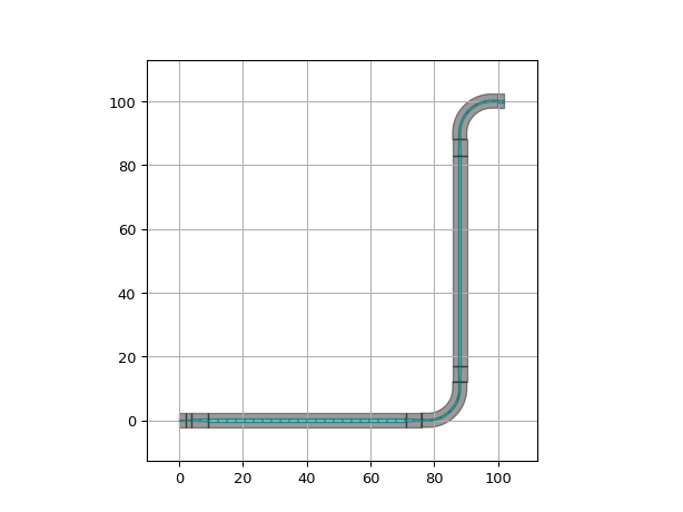
"""Demonstrates basic usage of ConnectManhattanTapered"""
import si_fab.all as pdk  # noqa: F401
import ipkiss3.all as i3
from picazzo3.traces.rib_wg.trace import RibWaveguideTemplate

# Trace template for the ports
tt1 = RibWaveguideTemplate()
tt1.Layout(core_width=0.5)
wg_tt1 = i3.Waveguide(trace_template=tt1)

# Trace template for the straight sections
tt2 = RibWaveguideTemplate()
tt2.Layout(core_width=0.8)

# Create a connection between two waveguides
circuit = i3.Circuit(
    insts={"wg1": wg_tt1, "wg2": wg_tt1},
    specs=[
        i3.Place("wg1", (0, 0)),
        i3.Place("wg2", (100, 100)),
        i3.ConnectManhattanTapered("wg1:out", "wg2:in", bend_radius=10, straight_trace_template=tt2),
    ],
)
circuit_layout = circuit.Layout()
circuit_layout.visualize()

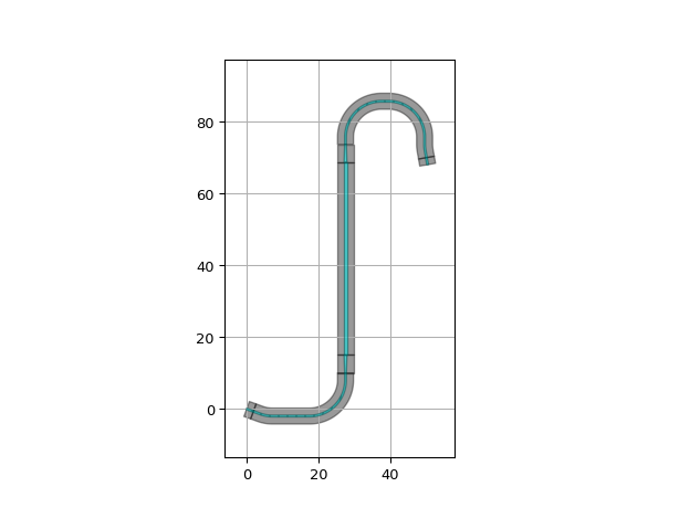
circuit = i3.Circuit(
    insts={"wg1": wg_tt1, "wg2": wg_tt1},
    specs=[
        i3.Place("wg1", (0, 0), angle=-20),
        i3.Place("wg2", (50, 70), angle=-80),
        i3.ConnectManhattanTapered("wg1:out", "wg2:in", bend_radius=10, straight_trace_template=tt2),
    ],
)
circuit_layout = circuit.Layout()
circuit_layout.visualize()
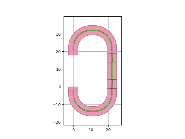
"""Customize the connection by setting the taper length and length of the straight sections"""
import si_fab.all as pdk  # noqa: F401
import ipkiss3.all as i3
from picazzo3.traces.wire_wg.trace import WireWaveguideTemplate

# Trace template for the ports
tt = WireWaveguideTemplate()
tt.Layout(core_width=0.5)

# Trace template for the straight sections
tt2 = WireWaveguideTemplate()
tt2.Layout(core_width=0.8)

# Create a connection
wg = i3.Waveguide(trace_template=tt)
circuit = i3.Circuit(
    insts={"wg1": wg, "wg2": wg},
    specs=[
        i3.Place("wg1", (0, 0), angle=-90),
        i3.Place("wg2", (0, 20), angle=-90),
        i3.ConnectManhattanTapered(
            "wg1:out",
            "wg2:in",
            taper_length=5,
            straight_section_lengths=[0, 0, 10, 0, 0],
            bend_radius=10,
            straight_trace_template=tt2,
        ),
    ],
)
circuit_layout = circuit.Layout()
circuit_layout.visualize()
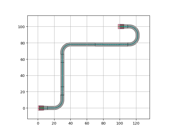
"""Example exploring more advanced features"""
import si_fab.all as pdk  # noqa: F401
import ipkiss3.all as i3
from picazzo3.traces.wire_wg.trace import WireWaveguideTemplate
from picazzo3.traces.rib_wg.trace import RibWaveguideTemplate

# Trace template for the ports
tt = WireWaveguideTemplate()
tt.Layout(core_width=0.5)
wg = i3.Waveguide(trace_template=tt)

# Trace template for the bends of the connecting waveguide
tt2 = RibWaveguideTemplate()
tt2.Layout(core_width=0.5)

# Trace template for the straight sections of the connecting waveguide
tt3 = RibWaveguideTemplate()
tt3.Layout(core_width=0.8)

# Create a connection between two waveguides
circuit = i3.Circuit(
    insts={"wg1": wg, "wg2": wg},
    specs=[
        i3.Place("wg1", (0, 0)),
        i3.Place("wg2", (100, 100), angle=180),
        i3.ConnectManhattanTapered(
            "wg1:out",
            "wg2:in",
            control_points=[(30, 30)],
            taper_length=10,
            straight_section_lengths=[0, 30, 20, 0, 0],
            straight_section_positions=[1] * 5,
            bend_radius=10,
            trace_template=tt2,
            straight_trace_template=tt3,
        ),
    ],
)
circuit_layout = circuit.Layout()
circuit_layout.visualize()
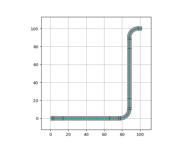
"""Example showcasing fixed bend usage"""
import si_fab.all as pdk  # noqa: F401
import ipkiss3.all as i3
from picazzo3.traces.rib_wg.trace import RibWaveguideTemplate

# Trace template for the ports
tt1 = RibWaveguideTemplate()
tt1.Layout(core_width=0.5)
wg = i3.Waveguide(trace_template=tt1)

# Trace template for the straight sections
tt2 = RibWaveguideTemplate()
tt2.Layout(core_width=0.8)

# Bend to use for the 90 degree sections
bend = i3.RoundedWaveguide(trace_template=tt1)
bend.Layout(shape=[(-10.0, 0.0), (0.0, 0.0), (0, 10.0)], bend_radius=10.0)

# Create a connection between two waveguides
circuit = i3.Circuit(
    insts={"wg1": wg, "wg2": wg},
    specs=[
        i3.Place("wg1", (0, 0)),
        i3.Place("wg2", (100, 100)),
        i3.ConnectManhattanTapered(
            "wg1:out",
            "wg2:in",
            taper_length=10,
            bend_radius=5,
            trace_template=tt1,
            straight_trace_template=tt2,
            fixed_bend90=bend,
        ),
    ],
)
circuit_layout = circuit.Layout()
circuit_layout.visualize()

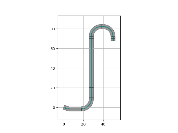
circuit = i3.Circuit(
    insts={"wg1": wg, "wg2": wg},
    specs=[
        i3.Place("wg1", (0, 0), angle=-20),
        i3.Place("wg2", (50, 70), angle=-90),
        i3.ConnectManhattanTapered(
            "wg1:out",
            "wg2:in",
            taper_length=10,
            bend_radius=5,
            trace_template=tt1,
            straight_trace_template=tt2,
            fixed_bend90=bend,
        ),
    ],
)
circuit_layout = circuit.Layout()
circuit_layout.visualize()
"""Demonstrates the usage of `start_taper_length`, `end_taper_length`, and `taper_length`"""
import si_fab.all as pdk  # noqa: F401
import ipkiss3.all as i3
from picazzo3.traces.rib_wg.trace import RibWaveguideTemplate
import matplotlib.pyplot as plt
from matplotlib import rc

def _line_with_arrows(ax, xdata, ydata, color, label=None, vertical=False):
    """helper function to plot with two-sided arrows"""
    ax.plot(xdata, ydata, label=label, color=color)
    anno_args = {"ha": "center", "va": "center", "size": 16, "color": color}
    if vertical:
        caps = "∨∧"
        offset = [[0, 0], [2, -2]]
    else:
        caps = "<>"
        offset = [[2, -2], [-0.5, -0.5]]
    ax.annotate(caps[0], xy=(xdata[0] + offset[0][0], ydata[0] + offset[1][0]), **anno_args)
    ax.annotate(caps[1], xy=(xdata[-1] + offset[0][1], ydata[-1] + offset[1][1]), **anno_args)

# Trace template for the ports
tt_start = RibWaveguideTemplate()
tt_start.Layout(core_width=0.25)
wg1 = i3.Waveguide(trace_template=tt_start)
tt_end = RibWaveguideTemplate()
tt_end.Layout(core_width=0.75)
wg2 = i3.Waveguide(trace_template=tt_end)

# Trace template for the bends sections
tt_bend = RibWaveguideTemplate()
tt_bend.Layout(core_width=2.0)

# Trace template for the straight sections
tt_straight = RibWaveguideTemplate()
tt_straight.Layout(core_width=4.0)

# Create a connection between two waveguides
circuit = i3.Circuit(
    insts={"wg1": wg1, "wg2": wg2},
    specs=[
        i3.Place("wg1", (0, 0)),
        i3.Place("wg2", (75, 100)),
        i3.ConnectManhattanTapered(
            "wg1:out",
            "wg2:in",
            bend_radius=10,
            straight_trace_template=tt_straight,
            taper_length=15.0,
            start_taper_length=20.0,
            end_taper_length=25.0,
            trace_template=tt_bend,
        ),
    ],
)

# Layout
circuit_layout = circuit.Layout()
circuit_layout.visualize(show=False, grid=False)

# Set font
rc("font", family="monospace")

# Annotate trace templates
plt.text(-5, 25, "tt_start")
plt.arrow(0, 21, 0, -8, width=2)
plt.plot((0, 0), (-8, 4), linestyle=":", color="black")
plt.text(67, 72, "tt_end")
plt.arrow(77, 78, 0, 8, width=2)
plt.plot((77, 77), (96, 108), linestyle=":", color="black")
plt.text(60, -2, "tt_bend")
plt.arrow(57, 0, -8, 0, width=2)
plt.plot((38, 28), (0, 10), linestyle=":", color="black")
plt.text(62, 48, "tt_straight")
plt.arrow(61, 50, -8, 0, width=2)
plt.plot((30, 43), (50, 50), linestyle=":", color="black")

# Annotate taper lengths
ax = plt.gca()
_line_with_arrows(ax, [2, 22], [-5, -5], "green", "start_taper_length")
_line_with_arrows(ax, [50, 75], [105, 105], "red", "end_taper_length")
_line_with_arrows(ax, [32, 32], [73, 88], "blue", "taper_length", vertical=True)
_line_with_arrows(ax, [32, 32], [12, 27], "blue", vertical=True)

# Configure and show the plot
plt.legend()
plt.xlim([-10, 100])
plt.ylim([-10, 140])
plt.show()
